background image

Bosch Automotive Diagnostics Equipment (Shenzhen) Limited 

KT400 system settings  |  ���  |  1�

���  |  1�

  |  1�

en

5.2 

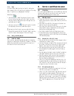
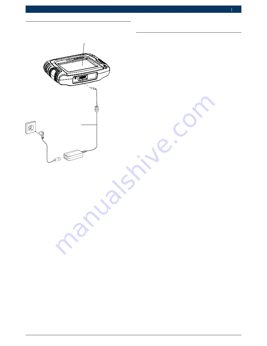
Selfcheck / upgrade connection

1

2

KT400/004

Fig. 4: 

Selfcheck / upgrade connection

1. Power adapter
2. KT400 host


i

Please don't connect KT400 host and diagnostic 
extension cable when selfcheck.

6. 

KT400 system settings

6.1 

Auxiliary function

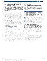
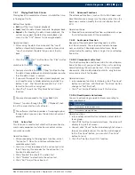
The auxiliary function include the language settings, 
system selfcheck, VCI selfcheck, touch calibration, cont-
rast adjustment, time and date setting, 

6.1.1 

Language Settings

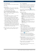
KT400 provides the multi-language system for user to 
switch languages.

Operation Steps:

1. 

Proceed to the language settings module and select 
the target language from the “Language Type Selec-
tion” box;

2. 

Click the “OK” button and the interface will prompt 
“Effective after System Restart”.'

3. 

The language settings will be effective after the 
system restart.

6.1.2 

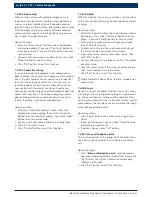
System selfcheck

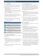
System selfcheck include check real-time clock, check 
SD card, check LCD display, check pilot lamp, check 
buzzer, check key-press, check LCD apheliotropic.

Operation steps:

1. 

Select the check items, one or more;

2. 

Click the "Start Check" button, then operation fol-
lowing the interface prompts;

3. 

When finished, interface will display the result.

6.1.� 

��� selfcheck

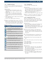
This function is used to detect whether the KT400 VCI 
is normal.

Operation Steps:

1. 

Ensure KT400 normally open;

2. 

Click the “Start Selfcheck” button and wait for the 
selfcheck completion and detection result display.

Summary of Contents for KT400

Page 1: ...VCI User Manual ...

Page 2: ......

Page 3: ...6 1 4 Touch calibration 14 6 1 5 Contrast adjustment 14 6 1 6 Time and date setting 14 6 1 7 Vehicle Logo Replacement 14 6 2 Network Setting 14 6 2 1 Network connection 14 6 2 2 Proxy Settings 15 6 3 Activation 15 6 4 Upgrade 15 6 4 1 Software Upgrade 15 6 4 2 VCI upgrade 15 6 4 3 System upgrade 16 6 4 4 Local upgrade 16 6 5 About equipment 16 6 5 1 System information 16 6 5 2 User information 16 ...

Page 4: ...f several steps e One step operation Instruction consisting of one step Intermediate result An instruction produces a visible inter mediate result Final result There is a visible final result on comple tion of the instruction 1 2 On the product Observe all warning notices on products and ensure they remain legible 2 Important notes Before start up connecting and opera ting Bosch Automotive Diagnos...

Page 5: ...al prosecution and to claim for damages Liability All data in this program is based where possible on manufacturer and importer details Bosch Automotive Diagnostics Equipment Shenzhen Limited does not accept liability for the correctness and completeness of software and data liability for damage caused by faulty software and data is ruled out Whatever the event Bosch Automotive Diagnostics Equipme...

Page 6: ...d in good time R R The test is to take the electrical engineering princip les relating hereto into account R R Upon request of the trade association a test manual is to be maintained into which specific entries are made 3 Safety instructions 3 1 Risk of electric shocks 3 1 1 Low voltages high voltages Hazardous voltages occur in both the lighting system and the electrical system of a motor vehicle...

Page 7: ...ternal damage The insulation of the high voltage wiring must be intact and undamaged Watch out for any abnormal deformation of the high voltage wiring 3 2 Danger of acid burning When exhaust gas measurements are taken the sampling hoses which are used release a highly caustic gas hydrogen fluoride that can cause acid burning in the respiratory system when heated to temperatures in excess of 250 C ...

Page 8: ...ns allow the engine to cool down first then disconnect the plug of the fan motor Route cables at a suitable distance from rotating parts Secure the trolley against rolling away by setting the brakes Do not place heavy objects on or lean on the sensor holder Transport and operate the equipment only in ac cordance with the operating instructions 3 4 Danger of burning When working on a hot engine the...

Page 9: ...haust gas are heavier than air and settle at the bottom of the pit Caution is also necessary when working on LPG driven vehicles Safety measures Always ensure effective ventilation and suction es pecially when working in a pit Always switch on and connect the suction plant in a closed area 3 7 Noise Noise levels in excess of 70 dB A can occur when measurements are carried out on a vehicle especial...

Page 10: ...iver R R Connect the equipment into an outlet on a circuit different from that to which the receiver is connec ted R R Consult the dealer or an experienced radio TV tech nician for help 3 10 Satety Warning R R Inspection shall be carried out in good ventilation Connect the exhaust pipe to outside if there is no enough ventilation R R Smoking and open fire are prohibited in the inspec tion R R The ...

Page 11: ...R R Certain inspection and maintenance basis are requi red to operate the instrument as well as electrical control system of the inspected automobile 3 12 Notes for operation of automobile ECU Pay attention to the following when diagnosing the au tomobile equipped with computer control system R R Do not put the magnetic objects such as radio loudspeaker near the computer because the magne tism of ...

Page 12: ...1 Diagnosis interface 2 Power interface 4 3 Connection Port 1 2 3 4 5 KT400 002 Fig 2 Connection port 1 USB interface Reserve 2 Pinter interface Reserve 3 Network communication interface Reserve 4 Trough of SD card 5 Micro USB 5 Equipment connection According to different functions the connection modes are including diagnostic connection selfcheck connec tion and firmware upgrade connection 5 1 Di...

Page 13: ...gs module and select the target language from the Language Type Selec tion box 2 Click the OK button and the interface will prompt Effective after System Restart 3 The language settings will be effective after the system restart 6 1 2 System selfcheck System selfcheck include check real time clock check SD card check LCD display check pilot lamp check buzzer check key press check LCD apheliotropic...

Page 14: ...licking the buttons and adjust the date and time 3 Select format and separator of date select time zone and format of time 4 Click OK button save the adjustments you can click Cancel button don t change the adjustments 6 1 7 Vehicle Logo Replacement There are two vehicle logo replacement methods single replacement and integral replacement with the single replacement taken as the default mode The p...

Page 15: ... and real name registration is recommended the E mail is used for the password retrieve and please fill your frequently used E mail upon submitting your individual information please remember your user name and password 6 4 Upgrade Upgrade include software upgrade VCI upgrade sys tem upgrade and local upgrade This function is available only after the product activati on If not display Not activati...

Page 16: ...and firmware VCI version KT400 will automatically detec tion VCI informations 7 Vehicle Diagnostic Main Interface of Vehicle Diagnosis No Description The main function area including vehicle diagnosis and service help The system function area including screenshot play back setting mainpage and help The display area for vehicle series including All Chinese American European Japanese Korean OBD II a...

Page 17: ...selection or brand search into diag nostic system 7 4 Diagnostic 7 4 1 Introduction to Main Interface of Diagnosis System After you access the diagnosis system the KT400 will display all diagnosis functions that can be achieved by this system No Description The display area for diagnosis functions it shows all dia gnosis functions of this system The display area for help information it shows the h...

Page 18: ... diagnosis software 7 4 3 2 Reading Freeze Frame In the engine management system the freeze frame function is supplementary to the fault code function It is basically used to freeze the relevant working con ditions of engine when engine fault arises helping the service personnel know the working conditions of the whole vehicle upon the fault occurrence Operation Steps 1 Select a fault code and cli...

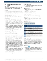
Page 19: ... of data stream 7 4 5 1 Capturing Data It capture the data stream being tested Operation Steps 1 Click the Capture Data button and start to capture the current value of data stream you may turn the pages to capture all data streams If you do not turn the pages only the data stream displayed in the current screen will be captured 2 Click the Save button to save the data stream read i i Before you a...

Page 20: ...data at any time and save them in the REC format under the specified folders You may click the Travel Recorder button at the Read Data Stream interface to proceed to the Travel Recorder interface Parameter Description Period according to the period you select the system will automatically match it with the selec table data streams the system provides 3 optio nal periods i e 250 ms 500 ms and 1000 ...

Page 21: ...em to proceed to the action test inter face There are three modes for the action test i e Enable Disable and Exit 3 Click Enable to activate the action test 4 Click Disable to deactivate the action test 5 Click Exit to quit the action test 7 4 9 Advanced Functions The advanced functions such as Write IQA Codes and Reset Maintenance Lamps are functions other than the basic ones and can modify the i...

Page 22: ...led 3 Click OK button to save 4 Click Cancel button to exit this function 7 4 10 5 Adjust With this function the user can achieve such functions as the security key matching and idle speed control val ve setup Operation steps 1 After into Adjust display there will display informa tion dialog If you click Continue button to enter adjust if you click Help button to Service Help 2 Enter group number ...

Page 23: ...the Read Version Informati on function has been enabled then the Fault Codes and the Data Streams will be gray and cannot be printed 3 Fill in the corresponding blanks with the information relevant to diagnosis report any blank marked with must be filled in otherwise it is impossible to print the diagnosis report 4 Just select a print mode either Print or Print to File to start printing 7 5 1 3 Pr...

Page 24: ...ace the KT400 near the stove or in the place where will be easily subjected to smoke erosion water entry and oil splashing R R Don t disassemble the host without permission R R If the vehicle test is not performed for a long time please periodically run the KT400 host to avoid being affected with damp 8 2 1 Maintenance of touch screen R R Do not click the screen before cursor appears when calibrat...

Page 25: ...ture 15 50 C Relative humidity 90 Input voltage DC 7 32V Micro SD card Pluggable SD card 2GB Micro Card Max 32GB Protection grade IP30 CPU Cortex A8 800MHz Dominant frequen cy Operation System Linux Monitor 7 800 480 LED Backlit color LCD Touch screen 7 Resistive touch screen 10 FAQ 1 How to judge SD card normally connect Answer If SD card has broken or abnormal connec tion the system will open st...

Page 26: ...Bosch Automotive Diagnostics Equipment Shenzhen Limited 5 F A Garden City Cyber Port Nanhai Road N 1079 Nanshan District Shenzhen 518067 China 400 000 5109 www bosch diagnostics com cn ...

Reviews: