Dimensioning instructions
Type L 309
Power Supply Module
15
1070 078 131-104 (00.05) GB
7. Dimensioning instructions
In principle, the load capacity of thyristors is predetermined by the type allocation to
specified max. welding transformer sizes.
CAUTION!
- The actual load of the thyristor should be checked by the user in each specific
case!
For this purpose, the load diagram is used. This load diagram indicates
the effective currents (I
RMS
in A) which the thyristor is capable of
switching as a function of
the duty cycle (ED in %) at max.
cooling agent temperature (in
_
C) and minimum
water throughput (in l/min.).
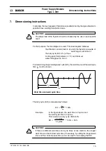
For determining the percentage duty cycle (ED), the weld time t
s
and the weld cycle
time t
sp
must be known.
Weld time and weld cycle time
t
s
t
sp
The duty cycle (ED) is calculated as follows:
ED=
t
s
t
sp
*100%
Example:
In the figure above, the weld time is 2 cycles and
the weld cycle time is 4 cycles.
This results in a duty cycle of ED=50%.
ED=
2 cycles
4 cycles
*100%=50%
CAUTION!
- If there are different weld times and cycle times at one machine, the longest
weld time and the shortest cycle time (if necessary, by adding the longest weld
time and the shortest pause time) are to be used for calculating the ED!
!
!
Summary of Contents for L 309 Series
Page 1: ...Power Supply Module Technical Information L 309 150 L 309 250 104 Edition ...
Page 3: ......
Page 5: ...Flexible Automation Type L 309 Power Supply Module 1070 078 131 104 00 05 GB ...
Page 15: ...Flexible Automation Type L 309 Power Supply Module Structure 2 1070 078 131 104 00 05 GB ...
Page 27: ...Maintenance Type L 309 Power Supply Module 14 1070 078 131 104 00 05 GB ...
Page 31: ...Dimensioning instructions Type L 309 Power Supply Module 18 1070 078 131 104 00 05 GB ...
Page 33: ...Fault messages Type L 309 Power Supply Module 20 1070 078 131 104 00 05 GB ...
Page 36: ...A 1 1070 078 131 104 00 05 GB 1070 078 131 104 00 05 GB TI WS AT VWS Printed in Germany ...


