Dimensioning instructions
Type L 309
Power Supply Module
16
1070 078 131-104 (00.05) GB
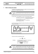
When the duty cycle has been calculated, the following load diagrams can be used
to verify the correct dimensioning of the thyristors:
Load diagram of types L 309.150 and L 309.151:
2500
Current carrying capacity I
RMS
[in A]
2000
1500
1000
500
ED
[in %]
0
2
5
10
20
50
100
0
Water cooling
4l/min;
30
_
C
150 kVA
100 kVA
30 cycles
weld time
max.
50% ED
L 309.150
L 309.151
1
Example:
Weld data of the machine: 100 kVA
Weld time:
t
s
= 10 cycles (< 30 cycles)
Duty cycle:
ED = 10 %
Current:
I
RMS
= 600 A
The intersection for ED = 10% and I
RMS
= 600 A found in the diagram
is below curve “1”.
Thus, the thyristor has been properly dimensioned.
Summary of Contents for L 309 Series
Page 1: ...Power Supply Module Technical Information L 309 150 L 309 250 104 Edition ...
Page 3: ......
Page 5: ...Flexible Automation Type L 309 Power Supply Module 1070 078 131 104 00 05 GB ...
Page 15: ...Flexible Automation Type L 309 Power Supply Module Structure 2 1070 078 131 104 00 05 GB ...
Page 27: ...Maintenance Type L 309 Power Supply Module 14 1070 078 131 104 00 05 GB ...
Page 31: ...Dimensioning instructions Type L 309 Power Supply Module 18 1070 078 131 104 00 05 GB ...
Page 33: ...Fault messages Type L 309 Power Supply Module 20 1070 078 131 104 00 05 GB ...
Page 36: ...A 1 1070 078 131 104 00 05 GB 1070 078 131 104 00 05 GB TI WS AT VWS Printed in Germany ...


