VARI-directional array
Installation | en
17
Bosch Security Systems B.V.
Installation manual
2018.06 | V1.3 |
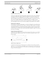
Figure
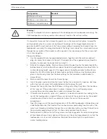
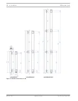
4.3: Bracket repositioning
Remove the hinged bracket to be repositioned by undoing the two M5 x 16 hex‑headed bolts
securing it to the back of the base unit (open the bracket at its hinge to gain access). The
spacing between the two threaded holes in the enclosure is the same as that between the
upper threaded hole in the base unit and the lower threaded hole in the extension unit when
the units are assembled. Reposition the hinged bracket so that it “straddles” the joint
between the two enclosures and refix using the original M5 bolts. The procedure for moving
the second bracket in the case of a line array assembly with two extension units is identical.
Removing of the front grille
Lay the extension unit to be attached down in a similar way. Remove the front grille by gently
lifting the grille at the locations of the “snap-on” fittings which hold it in place. Use the grille
removal tool provided for this. Note that the two end surfaces of the extension unit also have
two M5 holes and a multipin connector. Note the removable cover panel in the baffle at one
end of the extension unit; this is the end that needs to be attached to the base unit; orient the
extension unit accordingly.
Connect extension unit to base unit
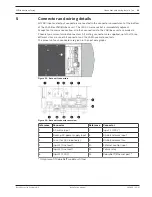
Remove the six self-tapping screws securing the cover panel of the extension unit and lift the
cover off. The open compartment gives access to the two M5 fixing holes/screws (1) in the
bottom surface.
Figure
4.4: Access to fixing screws
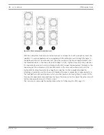
Carefully align the extension unit with the base unit, and mate the two multipin connectors
together (1, 2, 3). This procedure will probably need a second person to steady the base unit;
take care not to mate the connectors until the shells are accurately aligned, to avoid bending
any pins on the male connector.


