background image

Troubleshooting

Problem

Possible Causes

Action

No Sound

Amplifier

Connect a known working test speaker to the amplifier outputs. If
there is no sound, check all electronics are on, the signal routing is
correct, the source is active; the volume is turned up, and so on.
Correct/Repair/Replace as necessary. If there is sound, the problem is
in the wiring.

Wiring

Verify you have connected the correct wire pairs to the amplifier. Play
something at low level through the amplifier (for example, from a CD
player or tuner). Connect the test speaker in parallel with the
malfunctioning line. If the sound has gone or is very weak, the line has
a short in it (possibly a severe scrape, pinch, or staple puncture). If
the sound level is normal the wire is open (possibly a cut wire or
missed connection). Using the test speaker, move down the line and
test each connection/junction until you find the problem and correct
it. Observe proper polarity.

Verify you have the inputs and outputs connected to the correct wires.
If the subwoofer input panel is not correctly wired, there will be little
or no sound. Observe proper polarity.

Poor Low-
Frequency
Response

Speakers Wired Out-
of-Polarity

When two speakers are connected out of polarity (out of phase), the
low frequencies will cancel each other acoustically. Carefully observe
the wire markings or tracers on your speaker wires. Verify the
amplifier (+) terminal is connected to the red speaker terminals and
the amplifier (-) terminal is connected to the black speaker terminals.

Improperly Wired
Subwoofer Panel

Using a test speaker as described above, verify all amplifier and
speaker wires are connected to their proper terminals with the correct
polarity. Reversing just one set of amplifier wires can cut out all bass
output from the subwoofer.

Intermittent
Output such as,
Crackling or
Distortion

Faulty Connection

Check all connections at amplifier and speakers to ensure they are
clean and tight. If the problem persists, it may be in the amplifier or
wiring. See other actions above.

Constant Noise
such as Buzzing,
Hissing, Humming

Defective Amplifier
or other Electronic
Device

If the noise is present but no program material is playing, the likely
cause is the signal chain in the electronics. Evaluate each component
as necessary to isolate the problem.

Poor System
Grounding or
Ground Loop

Check and correct the system grounding, as required.

5

Premium Cabinet Loudspeakers

Troubleshooting | en

19

Bosch Security Systems B.V.

Installation manual

2017.08 | 01 | F.01U.345.357

Summary of Contents for LB20-PC15-4

Page 1: ...Premium Cabinet Loudspeakers en Installation manual ...

Page 2: ......

Page 3: ... Replacing the logo 18 5 Troubleshooting 19 6 Technical data 20 6 1 LB20 PC40 4 LB20 PC15 4 cabinet speakers 20 6 1 1 Dimensions 21 6 1 2 Frequency response and impedance 21 6 2 LB20 PC75 5 LB20 PC30 5 cabinet speakers 22 6 2 1 Dimensions 23 6 2 2 Frequency response and impedance 23 6 3 LB20 PC90 8 LB20 PC60 8 cabinet speakers 24 6 3 1 Dimensions 25 6 3 2 Frequency response and impedance 25 7 Wall...

Page 4: ...ure it is suggested the user install an extra suspension point back to the building structural supports This redundant safety point should have as little slack as possible less than 1 inch is preferable Figure 1 1 Redundant safety point 4 left 5 center 8 right Notices Old electrical and electronic appliances Electrical or electronic devices that are no longer serviceable must be collected separate...

Page 5: ... 100V white pair LB20 PC75 5D Cabinet speaker 5 8 Ohm black pair LB20 PC75 5L Cabinet speaker 5 8 Ohm white pair LB20 PC30 5D Cabinet speaker 5 70 100V black pair LB20 PC30 5L Cabinet speaker 5 70 100V white pair LB20 PC90 8D Cabinet speaker 8 8 Ohm black pair LB20 PC90 8L Cabinet speaker 8 8 Ohm white pair LB20 PC60 8D Cabinet speaker 8 70 100V black pair LB20 PC60 8L Cabinet speaker 8 70 100V wh...

Page 6: ...stem features LB20 PC40 4 LB20 PC15 4 Innovative mount system is included for quick simple and reliable installations Carefully engineered for outdoor environments IP54 without compromising performance Long throw 4 102 mm woofer housed in a fire rated ABS plastic enclosure for extended LF performance down to 75 Hz 40 W power handling provides for 103 dB maximum SPL 109 dB peak 70 100 V transformer...

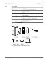
Page 7: ...g brackets G 2 Safety screw caps for the mounting brackets H 2 Covers for the locking bolt I 1 Installation manual Table 3 1 Components list for speakers without transformer A x2 B x2 D C x2 E x2 F x2 G x2 H x2 I Figure 3 1 Components list for speakers without transformer 3 2 Premium Cabinet Loudspeakers Introduction en 7 Bosch Security Systems B V Installation manual 2017 08 01 F 01U 345 357 ...

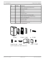
Page 8: ...r the mounting brackets H 2 Covers for the locking bolt I 1 Installation manual J 2 Flush input covers K 8 Screws for flush input covers Table 3 2 Components list for speakers with transformer A x2 B x2 D C x2 E x2 F x2 G x2 H x2 I J x2 K x8 Figure 3 2 Components list for speakers with transformer 8 en Introduction Premium Cabinet Loudspeakers 2017 08 01 F 01U 345 357 Installation manual Bosch Sec...

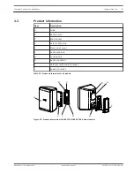
Page 9: ... Locking bolt H Audio connector I Safety screw hole for bracket J Speaker bracket Table 3 3 Product information for all models B G F E D C H I J A Figure 3 3 Product information LB20 PC75 5 LB20 PC30 5 model shown 3 3 Premium Cabinet Loudspeakers Introduction en 9 Bosch Security Systems B V Installation manual 2017 08 01 F 01U 345 357 ...

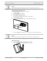
Page 10: ...damage to the product and personal injuries may occur Installing the wall bracket vertically To install the wall bracket vertically do the following 1 Drill a hole into the wall for the wire The size of the hole is dependent on the size of the wire used 2 Push the wire thru the hole 3 Adjust the wall bracket until the bubble is level 4 Install four mounting screws to secure the wall bracket to the...

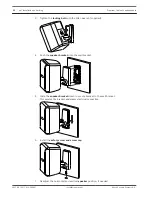
Page 11: ...ze of the wire used 5 Push the wire thru the hole 6 Install four mounting screws to secure the wall bracket to the wall 7 Connect the wires to wall bracket audio connectors as shown in the wiring section Notice If the speaker installation will be delayed cover it with the paint shield dust shield Installing the speaker 1 Loosen the locking bolt with the Allen wrench supplied 2 Adjust the horizonta...

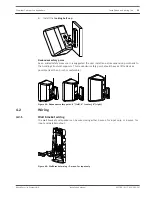
Page 12: ...down to secure bracket to the wall bracket This secures the bracket and makes electrical connection 6 Install the safety screw and screw cap 7 Readjust the horizontal and vertical speaker position if needed 12 en Installation and wiring Premium Cabinet Loudspeakers 2017 08 01 F 01U 345 357 Installation manual Bosch Security Systems B V ...

Page 13: ...s possible less than 1 inch is preferable Figure 4 1 Redundant safety point 4 left 5 center 8 right Wiring Wall bracket wiring The wall bracket and speaker can be wired using either 2 wires for input only or 4 wires for input and parallel output Figure 4 2 Wall bracket wiring 2 wires for input only 4 2 4 2 1 Premium Cabinet Loudspeakers Installation and wiring en 13 Bosch Security Systems B V Inst...

Page 14: ...onnection Notice These instructions apply to the speakers with and without transformers transformer version shown Available for all models except LB20 PC15 4 Wiring the speaker using the Euroblock connector To wire the speaker using Euroblock connector do the following 1 Wire the Euroblock connector 2 Adjust the tap settings if needed 4 2 2 14 en Installation and wiring Premium Cabinet Loudspeaker...

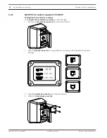
Page 15: ...r cover in place 7 Tighten all four screws to secure the weather cover Ensure the weather cover is secure 8 Adjust the wire length 9 Tighten the gland nut C 10 Readjust the horizontal or vertical speaker position See also Installing the speaker page 10 Transformer taps You can select the mode of operation for all models that have a transformer For the LB20 PC15 4 you can select the power tap for 7...

Page 16: ...lock connector from the input panel 2 Wire the jumper connector in the Euroblock according to the desired transformer settings 3 Plug the Euroblock connector into the input panel 4 Attach the flush input cover A A 4 3 1 16 en Installation and wiring Premium Cabinet Loudspeakers 2017 08 01 F 01U 345 357 Installation manual Bosch Security Systems B V ...

Page 17: ...evious step 3 Attach the flush input cover B B LB20 PC60 8 cabinet speakers 70V 100V Configuring the transformer settings To configure the transformer settings do the following 1 Select the desired power tap by using the rotary switch on the input panel A 2 If 8 ohm mode is desired remove the safety screw Safety screw A is shown in the previous step 4 3 2 4 3 3 Premium Cabinet Loudspeakers Install...

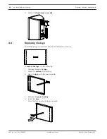
Page 18: ... do the following 1 Remove the existing logo 2 Clean the surface with alcohol 3 Align the logo with the square guide 4 Remove the paper backing 5 Insert the logo Press firmly to ensure the logo is applied 4 4 18 en Installation and wiring Premium Cabinet Loudspeakers 2017 08 01 F 01U 345 357 Installation manual Bosch Security Systems B V ...

Page 19: ...ired Out of Polarity When two speakers are connected out of polarity out of phase the low frequencies will cancel each other acoustically Carefully observe the wire markings or tracers on your speaker wires Verify the amplifier terminal is connected to the red speaker terminals and the amplifier terminal is connected to the black speaker terminals Improperly Wired Subwoofer Panel Using a test spea...

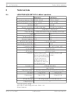
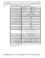
Page 20: ...transducer 4 inch 102 mm HF transducer 0 75 inch 20 mm Connectors Captive screws on wall bracket Removable locking 4 pin connector Euroblock 2 for connection to additional speakers in a distributed line Max wire size 12AWG 2 5 mm Captive screws on wall bracket Environmental IP54 per IEC 60529 Color Black or white Dimensions HxWxD 193 mm x 140 mm x 120 mm 7 6 in x 5 5 in x 4 7 in 3 Net weight 1 5 k...

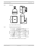
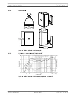
Page 21: ...Figure 6 1 LB20 PC40 4 LB20 PC15 4 dimensions Frequency response and impedance Figure 6 2 LB20 PC40 4 LB20 PC15 4 frequency response and impedance 6 1 1 6 1 2 Premium Cabinet Loudspeakers Technical data en 21 Bosch Security Systems B V Installation manual 2017 08 01 F 01U 345 357 ...

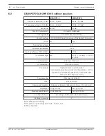
Page 22: ...mm HF transducer 0 75 inch 20 mm Connectors Captive screws on wall bracket Removable locking 4 pin connector Euroblock 2 for connection to additional speakers in a distributed line Max wire size 12AWG 2 5 mm Environmental IP54 per IEC 60529 Color Black or white Dimensions HxWxD 255 mm x 180 mm x 154 mm 10 0 in x 7 1 in x 6 0 in 3 Net weight 2 7 kg 5 9 lb 3 2 kg 7 0 lb Shipping weight pair 6 7 kg 1...

Page 23: ... Figure 6 3 LB20 PC75 5 LB20 PC30 5 dimensions Frequency response and impedance Figure 6 4 LB20 PC75 5 LB20 PC30 5 frequency response and impedance 6 2 1 6 2 2 Premium Cabinet Loudspeakers Technical data en 23 Bosch Security Systems B V Installation manual 2017 08 01 F 01U 345 357 ...

Page 24: ...r 8 in 203 mm HF transducer 1 in 25 mm Connectors Captive screws on wall bracket Removable locking 4 pin connector Euroblock 2 for connection to additional speakers in a distributed line Max wire size 12AWG 2 5 mm Environmental IP54 per IEC 60529 Color Black or white Dimensions HxWxD 390 mm x 250 mm x 224 mm 15 4 in x 9 8 in x 8 8 in 3 Net weight 5 1 kg 11 3 lb 5 8 kg 12 8 lb Shipping weight pair ...

Page 25: ... Figure 6 5 LB20 PC90 8 LB20 PC60 8 dimensions Frequency response and impedance Figure 6 6 LB20 PC90 8 LB20 PC60 8 frequency response and impedance 6 3 1 6 3 2 Premium Cabinet Loudspeakers Technical data en 25 Bosch Security Systems B V Installation manual 2017 08 01 F 01U 345 357 ...

Page 26: ...0 4 LB20 PC15 4 wall bracket dimensions 15 5 mm 0 6 in 93 5 mm 3 7 in 15 9 mm 0 6 in 4x 4 5 mm 4x 0 177 in 117 0 mm 4 6 in 51 8 mm 2 04 in 8 0 mm 0 315 in 15 9 mm 0 6 in 7 7 1 26 en Wall bracket dimensions Premium Cabinet Loudspeakers 2017 08 01 F 01U 345 357 Installation manual Bosch Security Systems B V ...

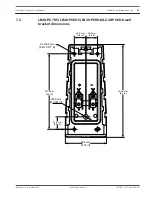
Page 27: ...ons 21 0 mm 0 83 in 127 0 mm 5 0 in 19 5 mm 0 8 in 156 0 mm 6 1 in 69 1 mm 2 72 in 4x 4 5 mm 4x 0 177 in 8 0 mm 0 315 in 19 5 mm 0 8 in 7 2 Premium Cabinet Loudspeakers Wall bracket dimensions en 27 Bosch Security Systems B V Installation manual 2017 08 01 F 01U 345 357 ...

Page 28: ...Bosch Security Systems B V Torenallee 49 5617 BA Eindhoven Netherlands www boschsecurity com Bosch Security Systems B V 2017 ...

Reviews: