background image

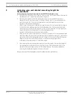
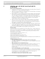
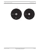
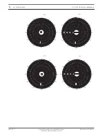
If the height cannot be reached, for example, by limitation of the ceiling, use an angle of
less than 8º. Focus the 0º-axis of the loudspeaker array to the desired maximum position
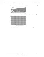
(see figure 4). Note that the table in diagram 1 and shapes in figures 2 and 3 are not valid
for this situation. Check in the listening area if the speech intelligibility is acceptable.

Background information:

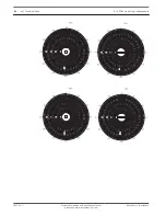
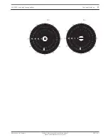
The shapes are defined in an anechoic environment. In these shapes at anechoic
conditions, you have a maximum of 6 dB sound pressure variation and much less
perceived frequency response variation. In areas with normal or high reverberations, less
sound pressure level variation takes place and the size of shapes will be bigger. The
perceived frequency response in this shape will then be almost constant.

When you go further than the maximum position of the listening area (beyond the
maximum distance from the loudspeaker array) only the sound pressure level will
decrease. There is almost no tone height variation. The decrease in sound pressure level
depends strongly on the reverberation of the room.

When you move too close to the loudspeaker array (less than the minimum distance from
the loudspeaker array) a lack of high tones will very soon occur.

Depending on the amount of reverberation in the room and the sound shadow (people or
objects in front of a listener who/that block the direct sound source), the speech
intelligibility at the furthest positions may be low. In these situations, it is better to use
more loudspeaker arrays to split the listening area.

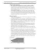
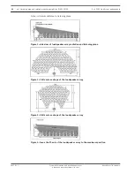
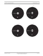
The side lines of the shapes of figure 2 and 3 are the -6 dB points related to the sound
pressure level on the 0º-axis.

To get the best speech intelligibility, define a listening area where the 4 kHz octave shape
covers the whole area.

To determine exactly where the edges of the listening are in your situation, you have to
carry out a practical test at the location where the loudspeaker array is installed. This is a
job for an experienced listener with well-trained ears. To do so, put pink noise through
the loudspeaker array. It is better to reduce the lower tones for this test, as they do not
contribute to speech intelligibility. Walk around in the listening area and listen to the high
tones. The places where the high tones decrease rapidly are the edges of the listening
area.

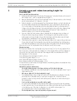
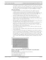
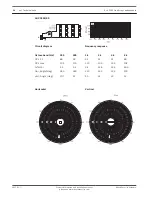
Diagram 1: relation between listening area and loudspeaker array mounting height
Diagonal line meanings:
B-line: maximum distance from loudspeaker array to last listener.
D-line: half-width listening plane at 1 kHz
F-line: listening plane side length of 4 kHz
C-line: listening plane length
E-line: half width listening plane of 4 kHz

XLA 3200 Line Array Loudspeakers

Listening area and related mounting height for XLA3210/00 | en

15

Bosch Security Systems

Product information and installation manual,

please see www.boschsecurity.com

2017.01 | |

Summary of Contents for LBC 3200/00

Page 1: ...XLA 3200 Line Array Loudspeakers LBC 3200 00 LBC 3201 00 LBC 3210 00 en Product information and installation manual please see www boschsecurity com ...

Page 2: ......

Page 3: ...elated mounting height for XLA3201 00 11 4 Listening area and related mounting height for XLA3210 00 14 5 Technical data 17 5 1 Additional technical data 20 XLA 3200 Line Array Loudspeakers Table of Contents en 3 Bosch Security Systems Product information and installation manual please see www boschsecurity com 2017 01 ...

Page 4: ...Installation 1 4 en Installation XLA 3200 Line Array Loudspeakers 2017 01 Product information and installation manual please see www boschsecurity com Bosch Security Systems ...

Page 5: ...XLA 3200 Line Array Loudspeakers Installation en 5 Bosch Security Systems Product information and installation manual please see www boschsecurity com 2017 01 ...

Page 6: ...6 en Installation XLA 3200 Line Array Loudspeakers 2017 01 Product information and installation manual please see www boschsecurity com Bosch Security Systems ...

Page 7: ...XLA 3200 Line Array Loudspeakers Installation en 7 Bosch Security Systems Product information and installation manual please see www boschsecurity com 2017 01 ...

Page 8: ...he loudspeaker array Approach 2 Minimized sound pressure level variation When less sound pressure level variation is desired an angle of 5º is recommended Note that this reduces the size of the total listening area compared to approach 1 and that the space very close to the loudspeaker array A in figure 2 is not part of the listening area Diagram 1 shows the relationship between A and the mounting...

Page 9: ...ion may be low In these situations it is better to use more loudspeaker arrays to split the listening area When you move further than the maximum position of the listening area more than the maximum distance from the loudspeaker array only the sound pressure level will decrease There is almost no tone height variation The decreasing of sound pressure level depends strongly on the reverberation in ...

Page 10: ...ray radiation mounted to the wall with a 5º angle Diagram 1 relation between listening area distance and loudspeaker array 10 en Listening area and related mounting height for XLA3200 00 XLA 3200 Line Array Loudspeakers 2017 01 Product information and installation manual please see www boschsecurity com Bosch Security Systems ...

Page 11: ... loudspeaker array to last listener is 15 m Tracing upwards from the 15 m point on the horizontal axis of diagram 1 to the diagonal B line and then sideways to the vertical axis the intersections with the other diagonal lines provide dimensions of the listening planes In this example F line listening plane side length of 4 kHz 11 1 m C line listening plane length 11 m E line half width listening p...

Page 12: ...front of a listener who that block the direct sound source the speech intelligibility at the furthest positions may be low In these situations it is better to use more loudspeaker arrays to split the listening area The side lines of the shapes of figure 2 and 3 are the 6 dB points related to the sound pressure level on the 0º axis To get the best speech intelligibility define a listening area wher...

Page 13: ...oudspeaker array Figure 3 4 kHz octave shape of the loudspeaker array Figure 4 focus the 0º axis of the loudspeaker array to the maximum position XLA 3200 Line Array Loudspeakers Listening area and related mounting height for XLA3201 00 en 13 Bosch Security Systems Product information and installation manual please see www boschsecurity com 2017 01 ...

Page 14: ... loudspeaker array to last listener is 15 m Tracing upwards from the 15 m point on the horizontal axis of diagram 1 to the diagonal B line and then sideways to the vertical axis the intersections with the other diagonal lines provide dimensions of the listening planes In this example F line listening plane side length of 4 kHz 11 1 m C line listening plane length 11 m E line half width listening p...

Page 15: ...front of a listener who that block the direct sound source the speech intelligibility at the furthest positions may be low In these situations it is better to use more loudspeaker arrays to split the listening area The side lines of the shapes of figure 2 and 3 are the 6 dB points related to the sound pressure level on the 0º axis To get the best speech intelligibility define a listening area wher...

Page 16: ...oudspeaker array Figure 3 4 kHz octave shape of the loudspeaker array Figure 4 focus the 0º axis of the loudspeaker array to the maximum position 16 en Listening area and related mounting height for XLA3210 00 XLA 3200 Line Array Loudspeakers 2017 01 Product information and installation manual please see www boschsecurity com Bosch Security Systems ...

Page 17: ...0 x 80 x 90 mm 23 62 x 3 15 x 3 54 in Weight 3 kg 6 6 lb Color Light gray matches RAL 9022 Environmental Operating temperature 25 ºC to 55ºC 13 ºF to 131 ºF Storage and transport temperature 40 ºC to 70 ºC 40 ºF to 158 ºF Relative humidity 95 Note The specification data is measured in an anechoic chamber free field The reference axis is perpendicular to the center point of the front grille The ref...

Page 18: ... x 90 mm 47 24 x 3 15 x 3 54 in Weight 6 4 kg 14 1 lb Color Light gray matches RAL 9022 Environmental Operating temperature 25 ºC to 55ºC 13 ºF to 131 ºF Storage and transport temperature 40 ºC to 70 ºC 40 ºF to 158 ºF Relative humidity 95 Note The specification data is measured in an anechoic chamber free field The reference axis is perpendicular to the center point of the front grille The refere...

Page 19: ...0 x 90 mm 47 24 x 6 3 x 3 54 in Weight 9 kg 19 8 lb Color Light gray matches RAL 9022 Environmental Operating temperature 25 ºC to 55ºC 13 ºF to 131 ºF Storage and transport temperature 40 ºC to 70 ºC 40 ºF to 158 ºF Relative humidity 95 Note The specification data is measured in an anechoic chamber free field The reference axis is perpendicular to the center point of the front grille The referenc...

Page 20: ...3 93 89 SPL max 102 104 106 108 108 104 Q factor 1 3 2 2 4 5 11 6 25 7 58 9 Hor Angle deg 360 360 220 190 130 100 Vert Angle deg 360 120 70 32 18 10 Horizontal Vertical 5 1 20 en Technical data XLA 3200 Line Array Loudspeakers 2017 01 Product information and installation manual please see www boschsecurity com Bosch Security Systems ...

Page 21: ...XLA 3200 Line Array Loudspeakers Technical data en 21 Bosch Security Systems Product information and installation manual please see www boschsecurity com 2017 01 ...

Page 22: ...22 en Technical data XLA 3200 Line Array Loudspeakers 2017 01 Product information and installation manual please see www boschsecurity com Bosch Security Systems ...

Page 23: ...XLA 3200 Line Array Loudspeakers Technical data en 23 Bosch Security Systems Product information and installation manual please see www boschsecurity com 2017 01 ...

Page 24: ... max 106 110 110 109 109 104 Q factor 2 2 3 2 6 5 12 6 23 4 53 3 Hor Angle deg 360 360 210 192 132 100 Vert Angle deg 107 67 50 33 22 12 Horizontal Vertical 24 en Technical data XLA 3200 Line Array Loudspeakers 2017 01 Product information and installation manual please see www boschsecurity com Bosch Security Systems ...

Page 25: ...XLA 3200 Line Array Loudspeakers Technical data en 25 Bosch Security Systems Product information and installation manual please see www boschsecurity com 2017 01 ...

Page 26: ...26 en Technical data XLA 3200 Line Array Loudspeakers 2017 01 Product information and installation manual please see www boschsecurity com Bosch Security Systems ...

Page 27: ...XLA 3200 Line Array Loudspeakers Technical data en 27 Bosch Security Systems Product information and installation manual please see www boschsecurity com 2017 01 ...

Page 28: ...L max 112 115 115 113 114 111 Q factor 2 2 2 7 6 3 10 8 22 6 32 3 Hor Angle deg 360 180 170 160 90 60 Vert Angle deg 100 60 55 34 18 10 Horizontal Vertical 28 en Technical data XLA 3200 Line Array Loudspeakers 2017 01 Product information and installation manual please see www boschsecurity com Bosch Security Systems ...

Page 29: ...XLA 3200 Line Array Loudspeakers Technical data en 29 Bosch Security Systems Product information and installation manual please see www boschsecurity com 2017 01 ...

Page 30: ...30 en Technical data XLA 3200 Line Array Loudspeakers 2017 01 Product information and installation manual please see www boschsecurity com Bosch Security Systems ...

Page 31: ...XLA 3200 Line Array Loudspeakers Technical data en 31 Bosch Security Systems Product information and installation manual please see www boschsecurity com 2017 01 ...

Page 32: ... CE label Figure 5 2 CE label Figure 5 3 CE label 32 en Technical data XLA 3200 Line Array Loudspeakers 2017 01 Product information and installation manual please see www boschsecurity com Bosch Security Systems ...

Page 33: ......

Page 34: ...Bosch Security Systems B V Torenallee 49 5617 BA Eindhoven Netherlands www boschsecurity com Bosch Security Systems B V 2017 ...

Reviews: