2 | LBC 3950/01 Ceiling Loudspeaker
Installation/Configuration Notes
Installation is easy with integral clips that securely hold
the ceiling loudspeaker in its cut-out. Ceilings from 9 to
25 mm thick can be accommodated. A template is also
provided for accurately marking the cutout in ceiling
panels. Wiring is via a connection block with push-type
terminals, making installation possible without using any
special tools. The terminal blocks have provision for loop-
through wiring. The transformer is delivered wired for 6 W
rated output power, but can easily be changed for other
connections using the color-coded wires and terminal
block.
u
v
w
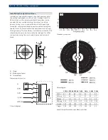
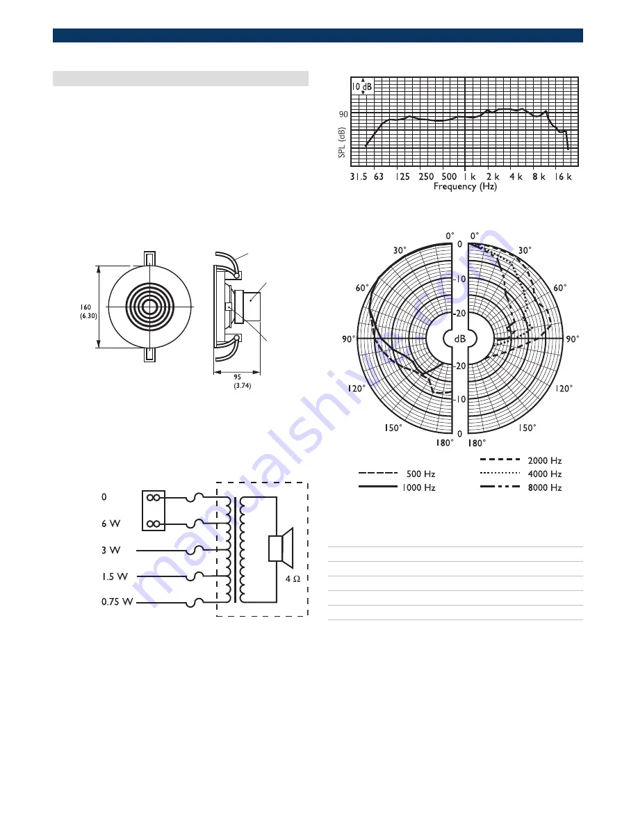
01 Clamp
02 Matching transformer
03 Terminal block
Dimensions in mm (in)
Circuit diagram
Frequency response
Polar diagram
125 Hz 250 Hz 500 Hz 1 kHz 2 kHz 4 kHz 8 kHz
SPL 1.1
87
88
86
88
89
91
89
SPL max. 95
96
94
96
97
99
97
Q-factor
4
5.6
2.6
3
3.8
8.1
15
Efficiency 0.16
0.14
0.19
0.27
0.26
0.19
0.06
H. angle
180
180
180
170
165
90
55
V. angle
180
180
180
170
165
90
55
Acoustical performance specified per octave

