2
| LBC 3951/11 Ceiling Loudspeaker
Installation/Configuration Notes
Installation is made easy with integral clips that securely hold
the ceiling loudspeaker in its cut-out. Ceilings from 9 to 25
mm thick can be accommodated. A template is also provided
for accurately marking the cutout in ceiling panels. Wiring is
via a connection block with push-type terminals, making
installation possible without using any special tools. The
terminal blocks have provision for loop-through wiring. The
transformer is delivered wired for 6 W rated output power, but
can easily be changed for other connections using the color-
coded wires and terminal block.
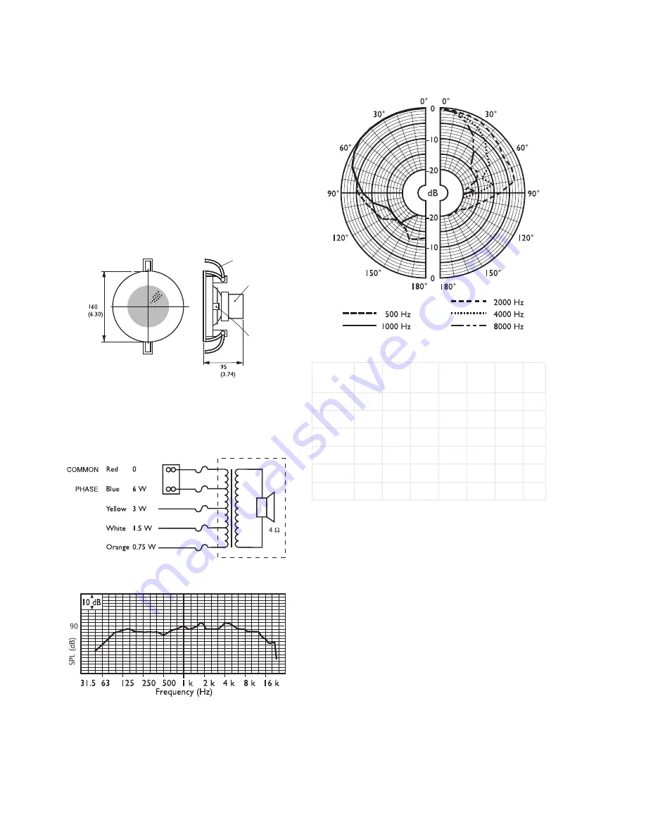
Dimensions in mm (inch)
Circuit diagram
Frequency response
Polar diagram
Quick reference table
01
Clamp
02
Matching Transformer
03
Terminal Block
X
Y
Z
Octave
band (Hz)
125
250
500
1k
2k
4k
8k
SPL 1.1
87
87
85
88
89
89
86
SPL max.
95
95
93
96
97
97
94
Q-factor
4
5.6
2.2
3.2
4.6
10.7
19
Efficiency
0.16
0.11
0.18
0.25
0.22
0.09
0.03
H. angle
180
180
180
170
160
80
60
V. angle
180
180
180
170
160
80
60


