background image

Installation and Wiring

The Bosch mounting system has been designed so that, if necessary, the installation can be
done from beneath the ceiling. In some cases with a suspended ceiling grid, however, it may
be easier to access from both the top and bottom of the ceiling tile during the installation
process. Typical installation hardware needed for either suspended ceilings or sheetrock
ceilings is included. The ceiling speaker assembly is held in place by mounting tabs that
securely grip the ceiling material. Input wiring is attached to a removable terminal block
connector that can be prewired if necessary before speaker installation to speed up the
installation process.

Step 1 — Cut the Hole

For suspended tile or sheetrock ceilings, cut out the hole either by tracing the cardboard
template or with a circular cutter set to the appropriate cutout size. If the wire has been pre-
installed, pull the wiring through the cutout hole.

Figure 4: Cut ceiling hole

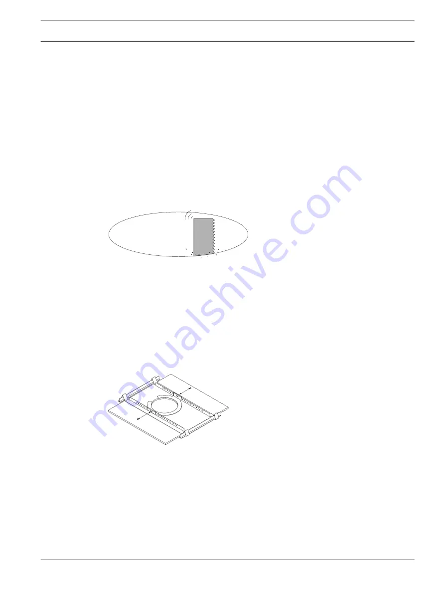
Step 2 — Install C-Ring and/or Tile Rails

All Bosch speakers come packaged with two types of backing hardware: a C-ring and two tile
rails. For suspended ceiling installations, insert the C-ring through the hole cut in the ceiling
tile. Place the C-ring around the hole with the tabs located as shown in Figure 5. Insert the tile
rails through the cut hole in the ceiling tile. Snap the two rails into the two tabs in the C-ring
and align the rails so that the ends extend OVER the T-channel grid on the side of the tile.
Secure the rails onto the C-ring tabs by inserting a screw though each tab into the rail, as
shown in Figure 5.

Figure 5: Secure rails to C-Ring

 
INSTALLATION NOTE: TILE RAILS AND C-RING
Each speaker comes with two tile rails which are designed to fit either standard 24-inch-wide
or 600-mm-wide tiles. It is important to note that the tile rail pieces do not actually attach to
the T-grid struts. The ends of the rails sit OVER the T-grid strut. Normally, the tile supports the
rails. The tile rails are pre-punched at regular intervals with holes along their length. This
allows the C-ring to be positioned at any point along the rail. If the tile comes out or falls
apart, the ends of the support rails fall onto the T-grid, which prevents the speaker assembly
from falling.

4

4.1

4.2

Prosound Ceiling Speakers

Installation and Wiring | en

9

Bosch Security Systems B.V.

Installation and User Instructions

2016.05 | 12 |

Summary of Contents for LC2-PC30G6-4

Page 1: ...Prosound Ceiling Speakers LC2 PC30G6 4 LC2 PC30G6 8 LC2 PC30G6 8L LC2 PC60G6 8H LC2 PC60G6 10 en Installation and User Instructions ...

Page 2: ......

Page 3: ...r Tile Rails 9 4 3 Step 3 Attach Wiring to the Ceramic Connector 10 4 4 Step 4 Mount the Speaker into the Ceiling 11 4 5 Step 5 Connect an Auxiliary Support Line 11 4 6 Step 6 Adjust Tap Selector 12 4 7 Step 7 Attach the Grille 12 5 Troubleshooting 14 6 Technical data 15 7 Appendices 17 7 1 Appendix A Painting the Speaker 17 Prosound Ceiling Speakers Table of Contents en 3 Bosch Security Systems B...

Page 4: ...ar If any sign of weakness or damage is detected remedial action should be taken immediately The user is responsible for making sure that the supporting surfaces and any additional hardware used is capable of supporting the loudspeaker Any hardware used to suspend a loudspeaker array that is not provided by associated with Bosch is the responsibility of others Caution The seismic tab auxiliary sup...

Page 5: ...ver and a 1 inch titanium coated tweeter with waveguide the LC2 PC60G 8H with a fully waveguide loaded 8 inch LF driver and a 1 inch titanium coated tweeter and the LC2 PC60G6 10 a true ceiling mounted subwoofer designed to augment and extend the full range model s low frequency response Important Features Model for model has superior performance to competing brands Comes with both 70V 100V or 8 o...

Page 6: ...2 PC30G6 8L The LC2 PC30G6 8L is the same as the LC2 PC30G6 8 but in a low profile installation package Ideal for tight ceiling spaces LC2 PC60G 8H The LC2 PC60G 8H is ideal for high ceilings and reverberant problem rooms Its exclusive ported waveguide coupled 8 inch driver provides excellent intelligibility and definition The 8 2HC s patent pending design provides great coverage control throughou...

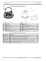
Page 7: ...rails C 2 C ring support D 2 Grille E 1 Owner s manual F 4 Support ring screws G 1 Cutout template H 2 Paint shield Figure 1 Packing list 3 2 Prosound Ceiling Speakers System overview en 7 Bosch Security Systems B V Installation and User Instructions 2016 05 12 ...

Page 8: ...h Ceiling Series Systems sold in pairs Model Part No Description LC2 PC30G6 4 4 coaxial speaker with horn loaded Ti coated tweeter LC2 PC30G6 8 8 coaxial speaker with horn loaded Ti coated tweeter LC2 PC30G6 8L Same as C8 2 above except with low profile backcan LC2 PC60G 8H 8 waveguide coupled coaxial speaker with horn loaded Ti coated tweeter LC2 PC60G6 10 10 High performance subwoofer 3 3 8 en S...

Page 9: ...rails For suspended ceiling installations insert the C ring through the hole cut in the ceiling tile Place the C ring around the hole with the tabs located as shown in Figure 5 Insert the tile rails through the cut hole in the ceiling tile Snap the two rails into the two tabs in the C ring and align the rails so that the ends extend OVER the T channel grid on the side of the tile Secure the rails ...

Page 10: ... the appropriate connector terminals as described below and screw down the hold down screw until tight using a small screwdriver Figure 6 Tighten with screwdriver When adding a subwoofer be sure to observe the correct polarity The LC2 PC60G6 10 subwoofer has been designed for optimum performance when used with the LC2 PC30G6 4 In order to maximize the low frequency output when used with the LC2 PC...

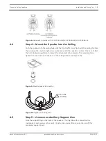
Page 11: ...nt tabs outward The remaining turns tighten the tabs down onto the back of the ceiling surface see Figure 10 Figure 9 Mount speaker into ceiling 8 in lbs 0 9 Nm Figure 10 Tighten mounting tabs Step 5 Connect an Auxiliary Support Line Note the support ring on the back of the speaker The ring allows for connection to a independent and secure anchor point Construction codes often require the use of t...

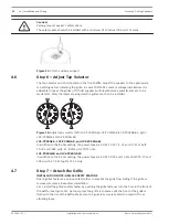
Page 12: ...e 8 ohm setting the power taps are 30 W 15 W 7 5 W and 3 7 W at both 70 7V and 100V with a 1 8 W tap for 70 7V only LC2 PC60G 8H and LC2 PC60G6 10 In addition to the 8 ohm setting the power taps are 60 W 30 W and 15 W at both 70 7V and 100V with a 7 5 W tap for 70 7V only Step 7 Attach the Grille INSTALLATION NOTE GRILLE SAFETY FEATURE Bosch grilles features a unique safety tether to prevent the g...

Page 13: ...e to pull down on the grille until that section of the grille comes out slightly Continue the same procedure around the perimeter of the grille loosening a portion at a time until the grille is removed 1 2 Figure 13 Attach the grille Prosound Ceiling Speakers Installation and Wiring en 13 Bosch Security Systems B V Installation and User Instructions 2016 05 12 ...

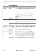
Page 14: ...per power tap setting Verify the power tap setting under the loudspeaker grille is appropriate for the installation and amplifier chosen Constant noise such as buzzing hissing or humming A faulty electronic device in the signal chain Loudspeakers cannot generate these sounds by themselves you may have a faulty electronic device in the signal chain Poor system grounding Check and correct the system...

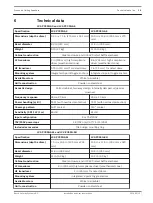
Page 15: ...5 Hz 20 kHz 50 Hz 20 kHz Power handling 8Ω 50 W with overload protection 75 W with overload protection Coverage pattern 130 conical 110 conical Sensitivity SPL 1 W 1 m 86 dB 91 dB Input configuration 8Ω 70V 100V 70V 100V power taps 1 8 70V only 3 7 7 5 15 30 W Included accessories Tile bridge mounting ring LC2 PC30G6 8L and LC2 PC60G 8H Specification LC2 PC30G6 8L LC2 PC60G 8H Dimensions depth x d...

Page 16: ... x diam 11 9 in x 12 6 in 303 mm x 320 mm Bezel diameter 13 8 in 350 mm Weight 15 5 lb 7 0 kg Cabinet construction Steel enclosure and UL94V 0 rated baffle and bezel LF transducer 10 in 260 mm high compliance driver weatherized cone Mounting system Integrated 4 point toggle anchors Available colors White paintable Grille construction Powder coated steel Acoustic design Ported cabinet internally da...

Page 17: ...two or more thin coats of paint If you are spraying hold the spray can at the angles shown in Figure 14 45 45 180 180 Baffle Can do not paint Figure 14 Spray painting angles If you are painting the grille also you must first remove the internal grille cloth Spray painting is strongly recommended If the grille is rolled or brush painted the grille may become clogged with paint and the sound quality...

Page 18: ......

Page 19: ......

Page 20: ...Bosch Security Systems B V Torenallee 49 5617 BA Eindhoven Netherlands www boschsecurity com Bosch Security Systems B V 2016 ...

Reviews: