background image

LTC 2810/91 | 

Instruction Manual

Safety Precautions

Bosch Security Systems | December 06, 2004

EN

| 4

Sécurité

Attention : l'installation doit exclusivement être réalisée par du
personnel qualifié, conformément au code national d'électricité
américain (NEC) ou au code d'électricité local en vigueur.

Coupure de l'alimentation. Qu'ils soient pourvus ou non d'un
commutateur ON/OFF, tous les appareils reçoivent de l'énergie une
fois le cordon branché sur la source d'alimentation. Toutefois,
l'appareil ne fonctionne réellement que lorsque 
le commutateur est réglé sur ON. Le débranchement du cordon
d'alimentation permet de couper l'alimentation des appareils.

ATTENTION : POUR ÉVITER TOUT RISQUE D'ÉLECTROCUTION,

N'ESSAYEZ PAS DE RETIRER LE CAPOT (OU LE PANNEAU

ARRIÈRE). CET APPAREIL NE CONTIENT AUCUN COMPOSANT

SUSCEPTIBLE D'ÊTRE RÉPARÉ PAR L'UTILISATEUR. CONFIEZ

LA RÉPARATION DE L'APPAREIL À DU PERSONNEL QUALIFIÉ.

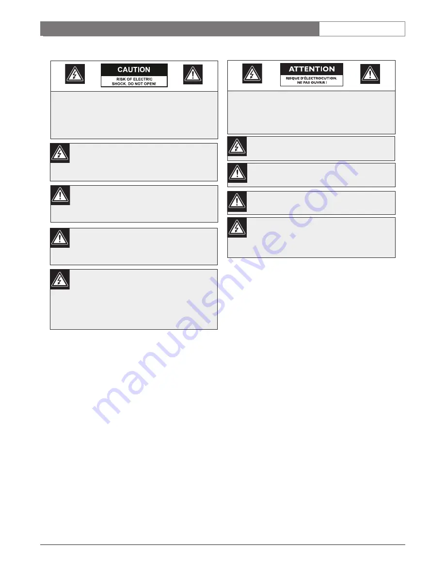
Ce symbole signale que le produit renferme une « tension
potentiellement dangereuse » non isolée susceptible de
provoquer une électrocution.

Ce symbole invite l'utilisateur à consulter les instructions
d'utilisation et d'entretien (dépannage) reprises dans la
documentation qui accompagne l'appareil.

Safety Precautions

Installation should be performed by qualified
service personnel only in accordance with the
National Electrical Code or applicable local
codes.

Power Disconnect. Units with or without 
ON-OFF switches have power supplied to the
unit whenever the power cord is inserted into the
power source; however, the unit is operational
only when the ON-OFF switch is in the ON
position. The power cord is the main power
disconnect for all units. 

CAUTION: TO REDUCE THE RISK OF
ELECTRIC SHOCK, DO NOT REMOVE COVER
(OR BACK). NO USER SERVICEABLE PARTS
INSIDE.  REFER SERVICING TO QUALIFIED
SERVICE PERSONNEL.

This symbol indicates the presence of
uninsulated “dangerous voltage” within the
product’s enclosure that can cause an electric
shock.

This symbol indicates the presence of
important operating and maintenance
(servicing) instructions in the literature
accompanying the appliance.

Summary of Contents for LTC 2810/91

Page 1: ...LTC 2810 91 Instruction Manual EN 10 in Color Monitor ...

Page 2: ...cal shock or other hazards 9 Safety Check Upon completion of servicing or repairs to the unit ask the service technician to perform safety checks to ensure proper operating condition 10 Power Sources Operate the unit only from the type of power source indicated on the label If unsure of the type of power supply to use contact your dealer or local power company For units intended to operate from ba...

Page 3: ...ns to avoid electrostatic discharge NOTE Grounded wrist straps must be worn and proper ESD safety precautions observed when handling the electrostatic sensitive printed circuit boards ATTENTION OBSERVE PRECAUTIONS FOR HANDLING ELECTROSTATIC SENSITIVE DEVICES FCC ICES INFORMATION U S A and Canadian Models Only This device complies with part 15 of the FCC Rules Operation is subject to the following ...

Page 4: ...enferme une tension potentiellement dangereuse non isolée susceptible de provoquer une électrocution Ce symbole invite l utilisateur à consulter les instructions d utilisation et d entretien dépannage reprises dans la documentation qui accompagne l appareil Safety Precautions Installation should be performed by qualified service personnel only in accordance with the National Electrical Code or app...

Page 5: ...eo A B input output looping with automatic 75Ω termination Y C input output looping with 75Ω slide switch 300 mV Audio input 1 W output capability 2 0 SERVICE If the unit ever needs repair service contact the nearest Bosch Security Systems Inc Service Center for authorization to return and shipping instructions Service Centers USA Phone 800 366 2283 or 717 735 6638 Fax 800 366 1329 or 717 735 6639...

Page 6: ...clockwise the skin tone becomes more red in color When turned clockwise the skin tone becomes more green in color NOTE There is no TINT control in PAL version 6 POWER Switch Press the switch to turn the monitor ON The INPUT INDICATOR will illuminate Press the switch again to turn the monitor OFF 7 Y C Indicator The lower green LED will be illuminated when the Y C is selected 8 Y C Selector Set the...

Page 7: ...s connected to the output connector the connection is placed into the open status by the multiple connection and high impedance automatically selected CAUTION Do not leave an unused cable connected to the monitor If a single cable is used it must be connected to the input connector for the 75Ω auto termination selector to function properly 4 0 TROUBLESHOOTING 5 0 MAINTENANCE Preventive maintenance...

Page 8: ...Up to 3 monitors can be connected using the loop through feature of this unit When multiple monitors are connected the same picture is viewed on all the connected monitors VCR SINGLE CONNECTION Video Camera MULTIPLE CONNECTION Video IN OUT Video Camera Digital CCD Camera IN OUT Audio OUT Audio IN YC B A YC B A YC B A YC B A ...

Page 9: ...elector Switches A B Y C Power On Off Rear panel Y C Impedance Switch Indicators LEDs Three green indicate Video A Video B and Y C S video when power is on Connectors Power input socket Video A Composite Video Two BNC 1 in 1 out Video B Composite Video Two BNC 1 in 1 out Audio A Two RCA phono jacks 1 in 1 out Audio B Two RCA phono jacks 1 in 1 out Y C S video Two Mini DIN 4 pin 1 in 1 out Power Co...

Page 10: ...LTC 2810 91 Instruction Manual Bosch Security Systems December 06 2004 EN 10 ...

Page 11: ...LTC 2810 91 Instruction Manual Bosch Security Systems December 06 2004 EN 11 ...

Page 12: ... Security Systems Inc 850 Greenfield Road Lancaster PA 17601 USA Tel 800 326 3270 Fax 1 717 735 6560 www boschsecurity com Bosch Security Systems B V P O Box 80002 5600 JB Eindhoven The Netherlands Tele 31 40 27 87113 Bosch Security Systems Pte Ltd 38C Jalan Pemimpin Singapore 577180 Republic of Singapore Tel 65 6 319 3486 ...

Reviews: