


16
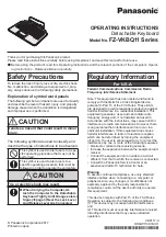
en | Installation
Allegiant Keyboards
F.01U.127.290 | 2.0 | 2009.03
Instruction Manual
Bosch Security Systems, Inc.
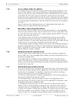
After the script has been entered, download the script into the Allegiant CPU. Reset the
system by powering the CPU off/on, or by entering Keyboard User Function 15 on an
operating keyboard. The specified port will begin to operate in the keyboard mode. The port
will remain in the keyboard mode unless manually cancelled by entering Ctrl-C several times
using Windows HyperTerminal program, operating at 9600 baud.
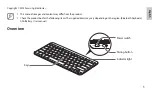
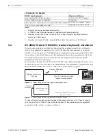
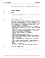
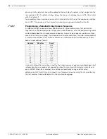
The keyboard can now be physically connected to the Allegiant according to details shown in
Figure 5.5
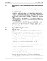
. For modem connections, refer to the next section and
Figure 5.6
.
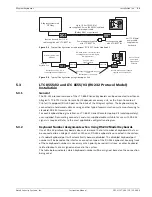
Once the keyboard is in communication with the Allegiant, camera and monitor numbers will
appear in the LED displays.
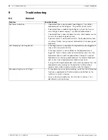
Figure 5.5
Direct Connection to Allegiant Console/Printer Port
5.3.4
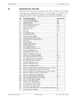
Modem Interface Information when Using RS-232 Model Keyboards
RS-232 model keyboards can be connected to an Allegiant via dial-up modem link. The
keyboard supports a rudimentary ability to dial a phone number of an attached modem.
Further details for the dial-up feature will follow, in the operating instructions.
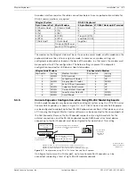
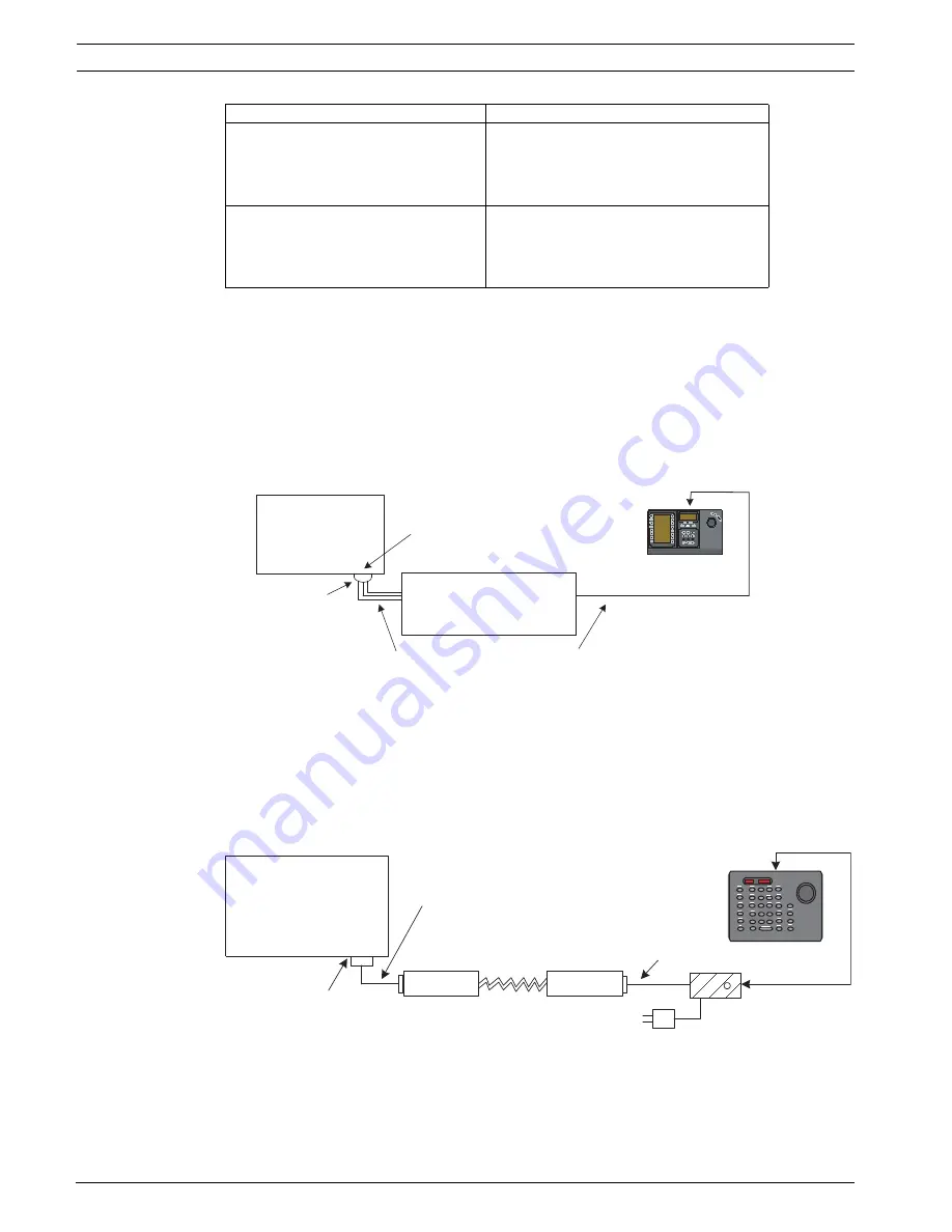
Figure 7 shows a typical system configuration using a modem connection.
Figure 5.6
Connection Using Dial-up Modem Link
Modem connected to Controller port
(LTC 8900 only)
Begin @boot
SET-PORT-RS232 0 4 8 0 1 1
_SET_KBD_MODE 0 1
break
Modem connected to Console port
(LTC 8900 only)
Begin @boot
SET-PORT-RS232 4 4 8 0 1 1
_SET_KBD_MODE 4 1
break
Keyboard interface connection type Command Script
Allegiant system main
CPU bay
CONSOLE port on Allegiant
system must be configured
for
RS-232 Keyboard mode
(refer to text for details)
User-supplied female
9-pin D connector
3 m (10 ft) data/
power cable
supplied with
keyboard
User-supplied cable or other link
suitable for
full duplex RS-232 transmissions
at 9600 baud
Console pin 2 (Rx) to Tx of link or directly to pin 3 of IntuiKey's 9 pin connector
Console pin 3 (Tx) to Rx of link or directly to pin 2 of IntuiKey's 9 pin connector
Console pin 7 (Gnd) to Data Gnd of link or directly to pin 5 of IntuiKey's 9 pin connector
1
2
3
4
5
6
7
8
9
0
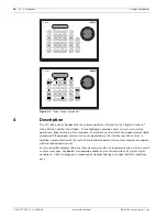
Shot
Mon
Prod
Clr
BOSCH
Allegiant system main
CPU bay
CONSOLE port on Allegiant
system must be configured
for
RS-232 Keyboard mode
Junction box and power
adapter supplied with
LTC 8557 kit
User-supplied
Allegiant-to-modem
interface cable
User-supplied dial-up
modem link
Modem
Modem
User-supplied
modem interface
cable
Summary of Contents for LTC 8555/00
Page 1: ...Allegiant Keyboards LTC 8555 Series en Instruction Manual ...
Page 2: ......
Page 39: ......