background image

PI -- 34.65d

Product Information MAGIC.SENS -- Product range

Page 24 of 42

BDL--4998121218

A23.en /09.02.2007

ST--FIR/ PRM1 / deh

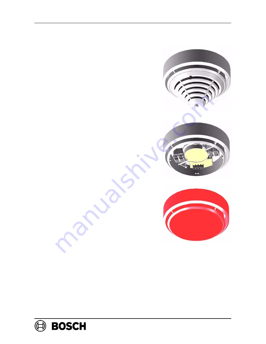
6.4. Detector Base Sirens MSS 300 / 400 / 401

If directly at the location of the fire the acoustic

signaling of an alarm is required, the detector

base sirens, available in 8 variants, are used.

-- Detector base siren MSS 300 in white and red,

for the conventional line technology and

connection via the C--point of the detector.

-- Detector base siren MSS 300 WS--EC in white,

for the conventional line technology with

external activation.

-- Detector base siren MSS 400 in white and red,

for the modern line technology LSN, with

power supply by the LSN.

-- Detector base siren MSS 401 in white and red,

for the modern line technology LSN, with

separate power supply.

Detector base type SA in white and red are

delivered with a cover plate and are intended only

for installation as independent signaling devices.

The integrated tone generator has 11 tones for

selection (incl. tones according to DIN 33404 and

EN 457) with acoustic pressure of max. 100 dBA,

depending on the type of tone selected.

With the LSN variants, the volume (4 levels) and also

the tone type are programmed via the fire panel.

The GLT variants are set using DIP switches and

a potentiometer.

Cable insertion “surface” and “concealed” possible.

Depending on the signal selected, individual tone

types can be set with connection to the Bosch

central unit UEZ 2000 LSN for pre--alarm and

alarm.

Summary of Contents for MAGIC.SENS series

Page 1: ...PRODUCT INFORMATION PI 34 65d BDL 4998121218 A23 en 09 02 2007 ST FIR PRM1 deh Page 1 of 42 MAGIC SENS This product information includes the entire MAGIC SENS product range ...

Page 2: ...viated GLT 8 3 4 Use in Explosive Areas 9 3 5 Use in Areas with Elevated Radioactivity 9 3 6 Use in Fire Barriers according to DIBt 9 4 Programming 10 4 1 MAGIC SENS OTC 410 LSN 11 4 2 MAGIC SENS OC 410 LSN 11 4 3 MAGIC SENS OT 400 E LSN 12 4 4 MAGIC SENS O 400 E LSN 12 4 5 MAGIC SENS T 400 E LSN 13 4 5 1 Sensitivity Classes according to EN 54 Part 5 13 5 Technical Data MAGIC SENS 14 5 1 Technical...

Page 3: ...rder Overview 29 8 1 Detector Variants 29 8 2 Detectors for Special Applications 29 8 3 Detector Base 30 8 4 Detector Base Sirens 30 8 5 Installation Accessories 31 8 6 Detector Accessories 31 8 7 MPA External Detector Alarm Display 31 9 Installation of the Detector Module 32 9 1 Locking the Detector Module in the Base 32 10 Dismounting the Detector Module 32 11 Maintenance and Service 33 11 1 Not...

Page 4: ...ctors The line technology variants are D LSN Local SecurityNetwork D GLT Gleichstrom conventional line technology The cooperation of engineers and designers created the timeless innovative design of this detector which integrates pleasantly into the ceiling With this design it is possible to reconcile the contradictory goals of a generous installation space and a small detector The placement of th...

Page 5: ...ght into a proportional electrical signal 2 2 2 Thermal Sensor temperature detector A thermistor 2 arranged on a resistance network serves as a thermal sensor on which an analog digital converter measures the temperature dependent voltage at cyclical intervals Depending on the detector class set the temperature measurement unit switches to an alarm state if the maximum temperature exceeds 54 C or ...

Page 6: ...old drift compensation of the chemical sensor D The EMVsecurity is with 30V m in the range 1 1000MHz and with 40V m in the cellular frequency ranges 415 466MHz and 890 960MHz significantly higher than that required by VdS 2110 VdS Schadenverhütung GmbH D Thanks to integrated isolators the LSN ring will continue to function in case of wire breakage or short circuit of a detector D Detector individu...

Page 7: ...ut gives rise to light smoke steam or dust 2 4 1 Features MAGIC SENS GLT D Active adjustment of the threshold drift compensation if the optical sensor becomes contaminated D Active adjustment of the threshold drift compensation of the chemical sensor D The EMVsecurity is with 30V m in the range 1 1000MHz and with 40V m in the cellular frequency ranges 415 466MHz and 890 960MHz significantly higher...

Page 8: ...rs see DIN VDE 0833 Part 2 and VDS 2095 minimum monitoring area 40m2 installation height maximum 7 5m for the T 400 E LSN or OT 400 E LSN installation height maximum 6m for the T 300 GLT or OT 300 GLT D Maximum cable length 1000m for J Y St Y n x 2 x 0 6 0 8 D Maximum permissible air speed 20 m s D When planning for fire barriers according to DIBt the following must be taken into account T 400 E L...

Page 9: ...able D Only fire detector cables that conform to DIN VDE 0814 may be used D The entire cable capacity Cmax may not exceed 1mF D The entire cable inductivity Lmax may not exceed 0 01H The cable type J Y ST Y08 according to DIN VDE 0815 Table 10 has a capacity of 120ηF with a length of 1000m Detector heating element D The use of a detector heating element MH 400 is not permissible 3 5 Use in Areas w...

Page 10: ...rs can be switched off Switch to optical sensitivity O unit low T unit switched off Switchover to thermo differential sensitivity T unit A2R O unit switched off Switchover to thermo maximum sensitivity T unit A2S O unit switched off With purely optical detectors O 400 E LSN the sensitivity of the optical sensors can be set on 3 levels Depending on the operation location the optical sensor in the d...

Page 11: ...se without vehicle traffic with combustion motors combined O Tmax Tdiff C low B high high Office daily operation combined O Tmax Tdiff C low B medium high With low sensitivity of the optical sensor the detector only triggers if smoke and also an increase of the CO concentration or the temperature is detected 4 2 MAGIC SENS OC 410 LSN Operation locations that can be selected in the Detector type Se...

Page 12: ...gh A2 high High board warehouse without vehicle traffic with combustion motors combined O Tmax Tdiff low B high Office daily operation combined O Tmax Tdiff low B mediu m 4 4 MAGIC SENS O 400 E LSN Operation location and recommended setting in the Sensitivity Operation location and recommended setting in the WinPara programming software Sensitivity O unit Theaters Concert Halls medium Warehouse wi...

Page 13: ...e In the sensitivity classes A1 A2S and BS the MAGIC SENS T 400 E LSN is operated as a pure thermo maximum detector Here in the class A2S the detector does not activate under 54_C and in class BS not under 69_C The sensitivity classes A2S and BS are therefore especially suitable for applications where over a longer period higher temperature rates of rise occur e g in kitchens or boiler rooms The s...

Page 14: ...ensation in optical unit and in gas measuring unit Operating voltage 15 V DC 33 V DC Current consumption 0 7mA Individual display LED red Alarm output per data word via two wire signal line Indicator output Open collector puts through 0 Volt via 1 5kΩ max 15mA Response sensitivity basic data O unit 0 15 dB m EN 54 T7 T unit EN 54 5 Thermomax unit 54 69 C Thermodifferential unit see table on page 1...

Page 15: ...S guidelines 40 m2 note VdS guidelines maximum mounting height 16 m note VdS guidelines 7 5 m note VdS guidelines permissible airspeed 20m s permissible operation temperature 20 C 65 C 20 C 50 C or 65 C Permissible relative humidity 95 non condensing Protection category according to EN 60 529 IP 30 Color code red ring Dimensions 99 5 x 52mm without base 120 x 63 5mm with base Housing material Colo...

Page 16: ...ncrease alarm resistance approximately 800Ω Indicator output Open collector puts through 0 Volt via 3 92kΩ max 15mA Response sensitivity basic data O unit 0 15 dB m EN 54 T7 Gas unit in the ppm range O unit 0 15 dB m EN 54 T7 T unit EN 54 5 Thermomaximum unit 54 C Thermodifferential unit see table on page 15 O unit 0 15 dB m EN 54 T7 max monitoring area 120 m2 note VdS guidelines maximum mounting ...

Page 17: ...m resistance approximately 800Ω Indicator output Open collector puts through 0 Volt via 3 92kΩ max 15mA Response sensitivity basic data T unit EN 54 5 Thermomaximum unit 54 C Thermodifferential unit see table on page15 T unit EN 54 5 Thermomaximum unit 54 C Thermodifferential unit see table on page15 max monitoring area 40m2 note VdS guidelines 40m2 note VdS guidelines maximum mounting height 6m n...

Page 18: ... 6 5 1646 PTB Physical Technical Federal Institute all types PTB Ex 01 20320 Belgium BOSEC Belgian Organization for O 400 E LSN TCC 2 286 g B g g Security Certification T 400 E LSN TCC 2 285 Bulgaria BG National Bureau Fire and Accident Protection Scientific Practical Institute for Fire and Accident Protection OT 400 E LSN O 400 E LSN T 400 E LSN OT 300 GLT O 300 GLT T 300 GLT IN 79 11 02 2000 Den...

Page 19: ...LT GTC 100162 Prie Lietuvos Respublikos Vidaus Reikalų G C T 300 GLT GTC 100160 p ų Ministerijos Gaisrinių Tyrimų Centras T 400 LSN GTC 100160 OT 400 LSN GTC 100165 OTC 410 LSN GTC 100165 Poland CNBOP OTC 410 LSN 1329 2003 PL Centrum Naukowo Badawcze Ochrony Przeciwpozarowej OC 410 LSN 1328 2003 Przeciwpozarowej OT 400 LSN 1327 2003 O 400 LSN 1326 2003 T 400 GLT 1325 2003 Russia RUS ÑÈÑÒÅÌA CEPTÈô...

Page 20: ...400 E LSN T 40137 ACR Czech Army 321 30 3 049 4 PAVÚS Brandatestationinstitut T 400 E LSN C 00 032 NBU National Security Bureau T 400 E LSN T 40138 ACR Czech Army applied for PAVÚS Brandatestationinstitut OC 310 GLT 08 0020 NBU National Security Bureau OC 310 GLT T 4015 2002 ACR Czech Army 321 30 3 049 2 PAVÚS Brandatestationinstitut OT 300 GLT 00 0033 NBU National Security Bureau OT 300 GLT T 401...

Page 21: ... the fire panel Contacts connected with the terminals guarantee a secure electric connection when installing the MAGIC SENS detector module 6 1 1 Installation instructions for the MS 400 detector base The detector base is screwed to the even dry subsurface with 2 screws at a distance of approximately 55 mm For cable insertion for surface mounting aP break out the prepared entry points X on the ext...

Page 22: ...ellow black red ye wh Cable insertion and feed out possible on the same side yellow b1 b2 LSN L b GLT white a1 a2 LSN L a GLT C indicator output see table p 11 13 red V black 0 V Terminals for looping through of the supply voltage for other LSN elements Keep screen sheath wire as short as possible and isolate For GLT conventional technology EOL end of line resistor End of line module External dete...

Page 23: ...r reliably against the penetration of condensed water Concealed and surface cable insertion possible 6 3 Additional Base MSC 420 The additional base MSC 420 was conceived specially for surface mounted cable ducts through cable protection conduits and it has 2 opposing pre cut inputs with 20mm and 2 additional opposing and prepared inputs for up to 28 mm diameter The additional base has a diameter ...

Page 24: ...SN with power supply by the LSN Detector base siren MSS 401 in white and red for the modern line technology LSN with separate power supply Detector base type SA in white and red are delivered with a cover plate and are intended only for installation as independent signaling devices The integrated tone generator has 11 tones for selection incl tones according to DIN 33404 and EN 457 with acoustic p...

Page 25: ...tallation height up to 4m and is designed for labels up to a size of approximately 65 x 34 mm 7 1 2 Support plate TP8 400 The support plate TP8 400 is intended for an installation height up to 8m and is designed for labels up to a size of approximately 97 x 44 mm 7 1 3 Labels for Self Labeling Labels by the Fa Zweckform have proven practical The self adhesive labels are made of sturdy white polyes...

Page 26: ...lene PP is pushed onto the installed detector base 7 4 Detector console MK 400 The detector console MK 400 is used for the DIBt conforming installation of detectors above frame sets etc The console is delivered with a pre installed base 7 5 Detector Heating Element MH 400 The detector heating element MH 400 is required if the detector is used in an environment where water condensation can occur su...

Page 27: ...conforms to the device category 3G gas group IIB and temperature class T6 in accordance with the European guideline 94 9 EG ATEX Thus the external detector alarm display may be used in Zone 2 areas where there is danger of explosion D The connection conditions see next page must absolutely be adhered to 7 6 2 Mounting hints D Mounting directly on the ceiling or wall D For surface mounted cable ins...

Page 28: ... FP 102 104 106 T 1 T 3 LSN BZ 500 UEZ 1000 UEZ 2000 UGM 2020 T 1 T 4 Connection when using in explosive areas of the Zone 2 Line technique Fire panels Terminals GLT UGM 2020 FP 102 FP 104 FP 106 T 1 T 3 LSN BZ 500 UEZ 1000 UEZ 2000 UGM 2020 T 1 T 4 Short circuit T 1 and T 2 limit T 4 to maximum of 20mA Terminal occupation T 1 Ground T 2 Input blinking LED blinks T 3 Input static LED lights up T 4...

Page 29: ...ermal 4 998 117 239 ST O 300 GLT Optical smoke detector 4 998 025 354 ST T 300 GLT Thermal detector LE Delivery unit ST Pieces 8 2 Detectors for special application areas Product ID LE Designation 4 998 117 239 ST O 300 ware monitoring Smoke detectors for fire barriers according to DIBt 4 998 107 056 ST T 300 FSA ware monitoring Thermal detectors for fire barriers according to DIBt 4 998 131 147 S...

Page 30: ...cable insertion 4 998 107 443 ST MSS 300 SA no detector can be put on Detector base siren red with cover plate C point activation for surface mounted and concealed cable insertion 4 998 098 974 ST MSS 400 LSN Detector base siren white supply via LSN C point activation via put on detector or external activation via the LSN for surface mounted and concealed cable insertion 4 998 107 445 ST MSS 400 L...

Page 31: ...9 PAK TP4 400 Support Plate for Detector Zones Identification up to 4m installation height 1 PACK 50 pieces 4 998 084 710 PAK TP8 400 Support Plate for Detector Zones Identification up to 8m installation height 1 PACK 50 pieces 4 998 025 369 ST SK 400 Basket guard against mechanical damage 4 998 035 312 PAK SSK 400 Protective dust cover 1 PACK 10 pieces 4 998 025 373 ST MH 400 Detector heating ele...

Page 32: ...cking the Detector Module in the Base The detector module can be locked in the base removal protection Detector modules are delivered with inactive locking The locking is activated by breaking the bars X out of the base and pushing them into the corresponding guides as shown in the pictures Locking activated X X Bars X installed Bars X forwards the breaking out but inactive 10 Dismounting the Dete...

Page 33: ...very 5 years OTC 410 LSN OC 410 LSN Depending on the lifespan of the gas sensor the detector OTC 410 LSN and OC 410LSN switches the C sensors off after 5 years of operation On the central unit the detector in question is displayed with EMERGENCY OPERATION and it continues to function as an OT or O detector The detector should be exchanged immediately in order to be able to keep using the higher de...

Page 34: ...ting data BG Adr module NVU LVM on which the detector or detector line is installed Address Installation address of the detector e g 10 03 The detector is in the detector group 10 and has the detector number 3 Brief info additional information entered during programming e g O400 to MSS400 means that the O 400 E LSN is installed together with a detector base siren MSS 400 Here you can also enter th...

Page 35: ...e detector The CO concentration displayed lies in the range between 0 normal state and 555 max measurement value of the sensor Operating hours counter display of the duration of operation since the initial start up of the detector Error code C malfunction cause effect and troubleshooting Error code Cause of trouble and troubleshooting 01000000 General C malfunction Possible causes malfunction of t...

Page 36: ...testing gas NOTE The transceiver must remain over the detector until the detector has been triggered The distribution of the test aerosol in the transceiver and thus the triggering time of the sensor can take up to 10 seconds D To test the CO sensor the same test device is used but exchange the testing gas bottle Solo A3 001 for the CO testing gas bottle For the CO test a testing gas application o...

Page 37: ...ors on the OC 310 GLT D Spray aerosol 1 to 2 seconds Do not remove test device from the detector the O unit triggers only approximately 60 seconds after the application of the test aerosol D Reset detector Thus the detector is switched into maintenance mode D Place CO gas bottle in the test device D Position test device on the detector D Apply CO gas for 1 2 to 1 second The C sensor triggers after...

Page 38: ...e used in the smoke extraction system RAS 100 LSN 12 Repair In case of defect the detector is exchanged completely 13 Disposal Packaging Film of the Fire Detectors with C Sensor The packaging bag of the multisensor detector with C sensor consists of tearproof PE ALU laminated film and may be thrown away with the garbage Defective detectors are exchanged and should be disposed of in accordance with...

Page 39: ... heat detectors consisting of detector tester 2 rechargeable battery bars and charging set with network and vehicle plugs 4 998 112 069 ST Telescope rod 1 m 3 38 m of fiberglass can be extended with max 3 extension rods 4 998 112 070 ST Extension bar of fiberglass 1 m 4 998 112 073 ST Transport bag for the test devices and their accessories LE Delivery unit ST Pieces PAK Pack 14 2 Spare parts for ...

Page 40: ...man Institute for Standardization EN European Standard GLT DCcurrentlinetechnology LED Light Emitting Diode LSN Local SecurityNetwork PI Productinformation PP Polypropylene UEZ Universelle Europazentrale Universal European Central UGM Universelle Gefahrenmeldezentrale Universal danger detector control unit uP unter Putz concealed VDE Association of German Electrical Engineers VdS VdS Schadenverhüt...

Page 41: ...PI 34 65d Product Information MAGIC SENS Product range Page 41 of 42 BDL 4998121218 A23 en 09 02 2007 ST FIR PRM1 deh 16 Notes ...

Page 42: ...Page 42 of 42 Bosch Security Systems Robert Koch Str 100 D 85521 Ottobrunn Info Service Telephone 49 89 6290 1039 Fax 49 89 6290 1039 www boschsecurity com info service de bosch com ...

Reviews: