


MBE Mounts and Adapters
MBE-27/28 Wall Mount Applications | en
9
Bosch Security Systems, Inc.
Installation Guide
| 3.0 | 2011.10
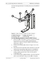
3.
Drill the four (4) holes in the installation location.
4.
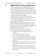
Using four bolts or studs (not supplied) with nuts,
washers, and lock washers, fasten the MBE-27/28 to its
mounting location and tighten all nuts securely.
Note
: The minimum diameter bolt (or stud) required is
6 mm (.25 in.).
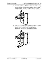
3.2
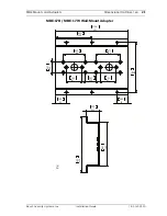
Mounting the MBE-27/28 with the MBE-17
Wall Adapter
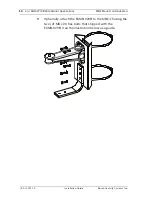
The MBE-17 Wall-Mount Adapter provides increased support for
the MBE-27 and the MBE-28 bracket. The MBE-17 also provides
a mounting location for the EXMB.020B L-bracket, a heavy-duty
bracket used to mount an additional piece of equipment, such
as an illuminator.
The combination of the MBE-27/28 and the MBE-17 can support
a total weight of 45 kg (100 lbs).
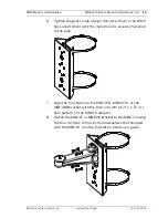
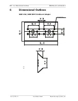
Note
: The MBE-17 Wall-Mount Adapter has two distinct hole
patterns for attaching various mounting brackets. Use the 94.2
x 40 mm (3.71 x 1.57 in.) hole pattern with the MBE-27/28
bracket. (Use the 86 x 40 mm hole pattern with the old
EXMB.023 or EXMB.028 bracket.)
Refer to
Section 6 Dimensional Outlines, page 20
, for detailed
dimensional drawings.
CAUTION!
Ensure that the mounting fasteners have a minimum pull-out
strength of 300 kg (661.4 lbs) per screw.
NOTICE!
The fasteners and mounting surface must be capable of
supporting a maximum load of 25 kg (55 lbs).
Summary of Contents for MBE Series
Page 1: ...MBE Mounts and Adapters MBE Series en Installation Guide ...
Page 2: ......
Page 25: ......


