94
en | Maintenance and upgrades
MIC Series IP Power Supply
F.01U.265.804 | 1.6 | 2012.08
User Manual
Bosch Security Systems, Inc.
6.6
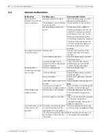
Malfunctions with iSCSI connections
6.7
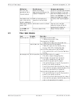
LEDs
The network video server has LEDs on its front and rear panels that show the operating status
and can give indications of possible malfunctions:
POWER LED
10/100 Base-T RJ45 socket
6.8
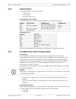
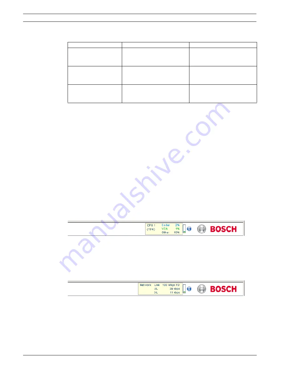
Processor load
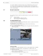
If the encoder is accessed via the Web browser, you will see the processor load indicator in
the top left of the window next to the manufacturer's logo.
You can obtain additional information to help you when troubleshooting or fine tuning the
unit. The values indicate the proportions of the individual functions on the encoder load,
shown as percentages. Move the cursor over the graphic indicator. Some additional numerical
values are also displayed.
6.9
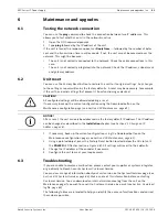
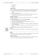
Network connection
You can display information about the network connection. To do this, move the cursor over
the
i
icon.
Malfunction
Possible causes
Recommended solution
After connecting to the
iSCSI target, no LUNs are
displayed.
Incorrect LUN mapping during
iSCSI system configuration.
Check the iSCSI system
configuration and reconnect.
After connecting to the
iSCSI target, "LUN FAIL"
appears below a node.
The LUN list could not be read,
as it was assigned to the wrong
network interface.
Check the iSCSI system
configuration and reconnect.
LUN mapping is not
possible.
Some iSCSI systems do not
support the use of an initiator
extension.
Delete the initiator extension on
the Identification configuration
page.
Does not light up: Encoder is switched off.
Lights up green:
Encoder is switched on.
Lights up red:
Startup in progress.
Flashes green:
Video connection established.
Flashes red:
Encoder is faulty, for example following failed firmware upload.
Green LED lights up:
Network connection established.
Orange LED lights up: Data transmission via network connection.
Link
Ethernet link type
UL
Uplink, speed of the outgoing data traffic
DL
Downlink, speed of the incoming data traffic

