30
en | Cabling
NEV 400 LSN Power
supply
2019-11 | 04 | F.01U.309.346
Bosch Security Systems B.V.
5.2
Connecting the thermistor
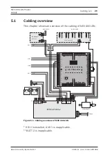
For an overview of the cabling, refer to
.
1.
Connect the thermistor cable (supplied, P/N F01U074759)
to terminal block 3 of the power supply.
2.
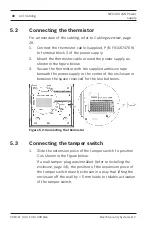
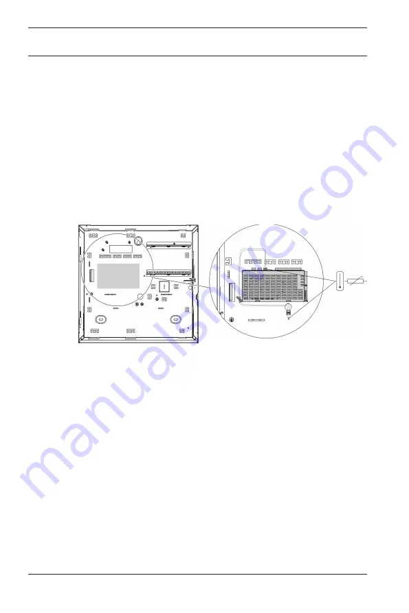
Mount the thermistor cable around the power supply as
shown in the figure below.
3.
Secure the thermistor with the supplied adhesive tape
beneath the power supply in the center of the enclosure in
between the space reserved for the two batteries.
Figure
5.2: Connecting the thermistor
5.3
Connecting the tamper switch
1.
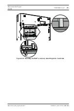
Slide the extension piece of the tamper switch to position
C as shown in the figure below.
If a wall tamper plug was installed (refer to
), the position of the expansion piece of
the tamper switch must be chosen in a way that lifting the
enclosure off the wall by > 5 mm leads to reliable activation
of the tamper switch.
Summary of Contents for NEV 400 LSN
Page 1: ...NEV 400 LSN Power supply ISP NEV400 120 en Installation manual ...
Page 2: ......
Page 43: ......

