F 002 DG9 A00
2013-04-16
|
Bosch Limited
Commissioning | ��� ���� | ��
��� ���� | ��
| ��
en
4.3
Connecting the external nitrogen
tank to the ��� ����
i
Execute the following procedure only if you have an
external nitrogen tank.
i
Ensure that the tank is mounted on a flat surface.
Allow sufficient space for opening the door of the
NTI 1000.
!
Do not tamper with the safety valve. Non-compliance
invalidates the warranty.
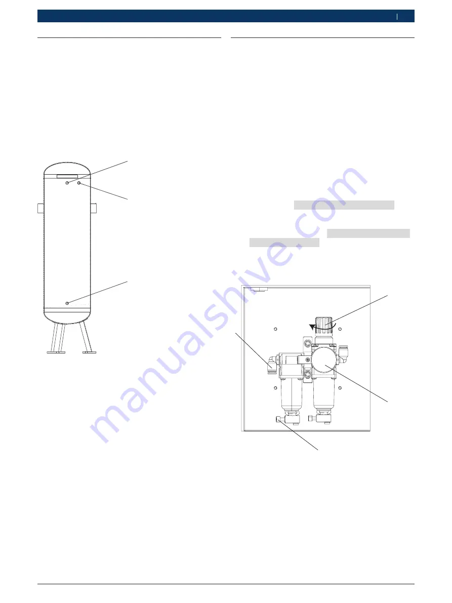
1
2
3
A00_32
Fig. 6:
External tank connections
1 Outlet of external tank
2 Slot for fastening safety valve
3 Inlet of the external tank
1.
Push the polyurethane hose from the Inlet port
(Fig. 2, Pos. 4) of the NTI 1000 into the inlet of the
external tank (Fig. 6, Pos. 3).
2.
Connect the other polyurethane hose from the outlet
(Fig. 6, Pos. 1) of the external tank to the outlet port
(Fig. 2, Pos. 5) of the NTI 1000.
"
The connections to the external tank are complete.
4.4
Powering on the ��� ����
4.4.�
Pressure sensor settings
1.
Switch on the compressor.
2.
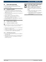
Observe the pressure gauge (Fig. 7, Pos. 3) of the
FRC.
?
The pressure should be at least 10 bar.
i
If the pressure does not read 10 bar, lift and rotate
the knob (Fig. 7, Pos. 1) in the clockwise direction
till the pressure reaches 10 bar.
3.
Switch on the mains supply.
4.
Switch on the master switch of the NTI 1000.
5.
Observe the tank pressure gauge on the door. Wait
until the tank pressure reaches at least 10 bar.
6.
Press
3
in the main menu.
?
The message
ATMOSPHERIC CALIBRATION
is
displayed.
?
Once the calibration to atmospheric pressure is
complete, the message
CALIBRATED TO ATMO-
SPHERIC PRESSURE
is displayed for a short du-
ration and the main menu is displayed.
"
The NTI 1000 is ready for operation.
1
2
3
4
A00_30
Fig. 7:
FRC unit
1 Knob
2 Pressure gauge
3 Drain
4 Input from compressor to FRC
Summary of Contents for NTI 1000
Page 1: ...NTI 1000 en Original instructions Nitrogen tire inflator ...
Page 2: ......
Page 19: ......


