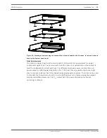
The device automatically switches to DC input in the event of failure of the mains supply
voltage. For this input, connect a 24-volt DC source to the DC INPUT input. The scope of
delivery for the device includes a 2-pin connector. Conductor cross-sections of 2 mm² to
6 mm² can be used.
Recommended connecting cable: flexible CU strand, LiY, 4 mm².
The DC input is protected against incorrect polarity and overload. The associated fuse is
located on the inside of the device and is not accessible from outside of the device. The
threshold of the internal audio peak limiters are lowered by 3 dB if DC is connected only.
Notice!
The DC input cannot be switched off. The power switch can only be used to switch off the
mains power supply.
CAN BUS
This section contains information about the connection of the device to the CAN BUS and the
correct setting of the CAN address.
Connection
The device has two RJ-45 jacks for the CAN BUS. The jacks are connected in parallel, and act
as an input and for daisy chaining the network. The CAN bus allows different data rates to be
used, where the data rate is indirectly proportional to the bus length. If the network is small,
data rates of up to 500 kbit/s are possible. In larger networks, the data rate must be
decreased (down to the minimum data rate of 10 kbit/s), please refer to section Configuring
the CAN baud rate.
Notice!
The data rate is preset to 10 kbit/s in the factory.
The following table explains the relationship between data rates and bus lengths/network
size. Bus lengths of over 1,000 m must be implemented only with CAN repeaters.
Data rate (in kbit/s)
Bus length (in meters)
500
100
250
250
125
500
62.5
1000
Table 6.1: Data rate and bus length of the CAN BUS
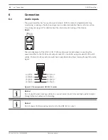
The following diagrams show the assignment of the CAN port/CAN connector.
6.4
20
en | Connection
PAVIRO Amplifier
18-Jun-2015 | 04 | F01U306898
Operation manual

