English |
23
– Stir the spray material thoroughly.
Using spray material at room temperature will yield a bet-
ter spray pattern.
– Dilute the spray material if necessary.
If the spray test does not produce a good spray pattern,
dilute in 5 % increments until an optimal spray pattern is
achieved.
Spray material
Recommended
dilution
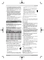
Wood preservatives, oils, glazes, impreg-
nations, water
0 %
Solvent-dilutable or water-dilutable (re-
commended) lacquers, primers, anti-rust
primers, radiator lacquers, thick-coat
glazes
0–10 %
Emulsion paints and latex paints (wall
paints)
At least 5 %
Dilution table
Spray mater-
ial
[ml]
Diluting agent [ml] for dilution
5 %
10 %
15 %
300
15
30
45
400
20
40
60
500
25
50
75
600
30
60
90
700
35
70
105
800
40
80
120
Filling the spray material (see figures C1–C2)
Note:
Remove the air hose
(19)
before pouring in spray ma-
terial (quarter turn of the bayonet lock
(20)
anticlockwise;
pull the bayonet lock
(20)
out of the port
(9)
).
– When using large buckets, pour the spray material into a
smaller transfer bucket
(13)
if necessary (e.g. 10 l wall
paint into an empty 2.5 or 5.0 l bucket).
– Hold the spray gun in place with one hand and
use the other hand to turn the container
(7)
towards the open symbol.
– Pull the spray gun off the container
(7)
.
– If you are using already opened spray material, place the
thoroughly cleaned filling sieve
(12)
on the container
(7)
to hold back any lumps of paint when pouring in.
– Pour the spray material into the container
(7)
up to no
more than the 1000 mark
.
– Put the spray gun on the container
(7)
. Turn
the container
(7)
towards the close symbol
until you hear the lock ring
(6)
engage.
– Carry out a test-spray run on a test surface.
If the spray pattern is optimal, you can begin spraying.
or
If the spraying results are unsatisfactory or no paint is emit-
ted: (see "Troubleshooting", page 26)
Starting Operation
u
Pay attention to the mains voltage.
The voltage of the
power source must match the voltage specified on the
rating plate of the power tool.
u
Make sure that the base unit cannot draw in dust or
other contamination during operation.
u
Make sure never to spray on the base unit.
u
Stop spraying if fluid escapes from places other than
the intended nozzle during spraying, and restore the
spray gun to its proper condition.
There is a risk of elec-
tric shock.
u
Do not direct the fine-spray system against yourself,
other persons or animals.
Switching On (see figure D)
– Check whether the correct nozzle cap is fitted (see "Chan-
ging the Nozzle Cap (see figures
– Plug the mains plug into a plug socket.
– Grasp the spray gun by the handle and point it at the tar-
get area.
– Set the sliding switch
(25)
to the required application to
regulate the air flow (see "Setting the Air Flow
(see figure
– Pull the trigger switch
(5)
on the spray gun.
Note:
Air always flows out at the air cap
(2)
when the base
unit is switched on.
Switching Off
– Let go of the trigger switch
(5)
and slide the sliding
switch
(25)
all the way to the left (position
◯
).
– Pull the mains plug from the plug socket.
Working Advice
Spraying (see figures E–H)
Note:
Pay attention to the wind direction when you are using
the power tool outdoors.
– Firstly, carry out a spray test and adjust the spray pattern
and the spray material volume according to the spray ma-
terial.
For adjustments, see the following sections.
– Make sure to hold the spray gun with a uniform clearance
of 20–25 cm vertical to the object being sprayed.
– Begin the spraying procedure outside the target area.
– Move the spray gun evenly horizontally or vertically ac-
cording to the spray pattern configuration.
An even surface quality can be achieved when the spray
paths overlap by 4–5 cm.
– When spraying horizontal objects or spraying overhead,
hold the spray gun at a slight angle and move back from
the sprayed surface.
Risk of tripping! Be aware of potential obstacles.
– Avoid interruptions when spraying the target area.
Guiding the spray gun evenly will provide uniform surface
quality.
A non-uniform spraying angle and distance will lead to heavy
formation of paint mist and consequently an uneven surface.
Bosch Power Tools
1 609 92A 685 | (09.09.2021)
Summary of Contents for PFS 3000-2
Page 5: ... 5 max 20 25 cm C2 D E F G 13 12 7 25 Bosch Power Tools 1 609 92A 685 09 09 2021 ...
Page 6: ...6 H I J L K 22 4 23 21 1 609 92A 685 09 09 2021 Bosch Power Tools ...
Page 322: ...322 عربي 1 609 92A 685 09 09 2021 Bosch Power Tools ...
Page 326: ...IV 1 609 92A 685 09 09 2021 Bosch Power Tools ...


