16
en | Installation
Battery Charger
180110011Aa | V1.1 | 2011.05
Installation and Operation manual
Bosch Security Systems B.V.
5
Installation
Before installing the battery charger into the 19" rack, the battery jumper setting must be
carried out.
5.1
Battery jumper setting
The battery charger takes every 4 hours a resistance measurement (Ri) of the battery
including connections and battery fuse if the total output current (main plus auxiliary) is
<12 A.
For each battery charger type a jumper is located at the daughter board to set trigger
thresholds for the resistance and allowed discharge current.
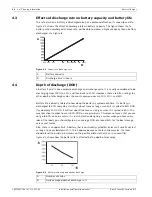
Figure 5.1
Location of the battery jumper of the PLN-24CH12 (similar location for the PRS-48CH12)
The jumper is set on the ‘75’ position as factory setting. Any other position of the jumper is
equal to the ‘50’ position.
Exceeding the Ri thresholds is signalled as a battery fault (see section
3.4.1
) and means that
the battery charger with its associated battery will not have the required back-up duration in
case of mains failure.
To avoid initiating this fault, take care of the following:
–
Use authorized batteries (see
Section 7 Configuration
).
–
Use short battery cables with a diameter as large as possible (35 mm² max.):
–
For a cross-section of 10 mm², the resistance is 2 m
Ω
/m
–
For a cross-section of 16 mm², the resistance is 1.25 m
Ω
/m
–
For a cross-section of 25 mm², the resistance is 0.8 m
Ω
/m
–
For a cross-section of 35 mm², the resistance is 0.6 m
Ω
/m.
–
Example: for battery cables (+ and -) 1.5 m in length and with a cross-section of 10 mm²,
the resistance is 6 m
Ω
.
–
The connections should be realized properly in order to generate as low resistance as
possible.
–
An additional battery fuse will add about 1 to 2 m
Ω
.
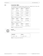
Jumper setting
Voltage
Threshold (Ri)
Battery capacity
Max. allowed
discharge current
75 (factory default) 24 Vdc
13 m
Ω
±10%
86 to 225 Ah
150 A
48 Vdc
26m
Ω
±10%
86 to 225 Ah
150 A
50
24 Vdc
20m
Ω
±10%
65 to 225 Ah
100 A
48 Vdc
40m
Ω
±10%
65 to 225 Ah
100 A
100 75 50 25
Summary of Contents for PLN-24CH12
Page 1: ...Battery Charger PLN 24CH12 and PRS 48CH12 en Installation and Operation manual ...
Page 2: ......
Page 34: ......


