background image

General system requirements

Make sure the following general system requirements are observed:

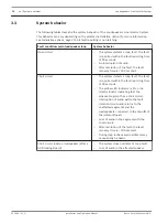
The maximum loudspeaker load of a loop is 500 watts.

The overload power setting of the Isolator Board must not be larger than 25% of the
amplifier power to that loop.

The maximum cable length is 1000 m (3281 ft) per loop.

The public address system is a 100 volt constant voltage system (e.g. Bosch Plena, Bosch
Praesideo).

The power consumption of the loudspeakers is between 0 and 100 watts.

The ground connections between system components is securely made.

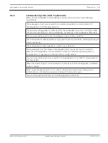
Plena VAS system requirements

Make sure the Plena VAS system conforms to the following requirements:

The Plena VAS system is correctly configured and installed, according to the Installation and
User Instructions.

The Plena VAS system is setup as a two-channel system.

One router is connected to one Master Unit. To ensure for correct ground short detection,
do not connect zones from one router to more than one Master Unit or vice versa (this also
applies to the router inside the Voice Alarm Controller).

Each router has a set of amplifiers for music and calls. To ensure for correct ground short
detection, do not connect an amplifier to more than one router.

To ensure correct ground short detection on the Master Unit, the ground short slave switch
on one connected loop is set to off, and the ground short slave on the other loops is set to
on.
Each zone output is connected to one loop input.

The fault outputs of the Loudspeakers Line Isolator System are connected to the input
triggers of the Plena VAS system. Each loop fault output can be individually connected to the
Plena VAS system, or all fault outputs can be connected in series.

On the Master Unit, the general fault output is connected in series with the master loop fault
outputs. The general fault output is a normally energized fail-safe relay.

The chosen contact inputs on the voice alarm system are configured as fault input with the
description “EOL + ground short”. The Plena VAS system will then indicate a zone fault and a
ground short simultaneously.
The output contacts of the Loudspeaker Line Isolator System Master will distinguish
between loudspeaker line failures and a ground short.

The short circuit check in Plena VAS is switched off.

The ground short detection in Plena VAS is switched off.

The Plena VAS system has software version 3.00.03 or higher.

The Plena VAS system has hardware version 3.0 or higher.


4.2.1

4.2.2

Loudspeakers Line Isolator System

Planning | en

17

Bosch Security Systems B.V.

Installation and Operation Manual

2014.03 | V1.1 |

Summary of Contents for PM1-LISD

Page 1: ...Loudspeakers Line Isolator System PM1 LISM6 PM1 LISS PM1 LISD en Installation and Operation Manual ...

Page 2: ......

Page 3: ... 3 3 Installation option 3 Loudspeakers connected between Isolator Boards 25 4 3 4 Combining installation options 27 5 Installation 28 5 1 Install Master Unit in 19 inch rack 29 5 2 Install an Isolator Board or DC Blocking Board in a housing 29 5 3 Install an Isolator Board or DC Blocking Board in a loudspeaker 30 5 4 Install a DC blocking capacitor in a loudspeaker 30 5 5 Install an end of line r...

Page 4: ... grounding 53 10 3 Perform a Walk Test 53 11 Technical data 54 11 1 Master Unit 54 11 2 Isolator Board 57 11 3 End of line resistor 57 11 4 DC Blocking Board 58 11 5 Approvals 58 11 6 Compliance 58 4 en Table of Contents Loudspeakers Line Isolator System 2014 03 V1 1 Installation and Operation Manual Bosch Security Systems B V ...

Page 5: ...nd electronic appliances Electrical or electronic devices that are no longer serviceable must be collected separately and sent for environmentally compatible recycling in accordance with the European Waste Electrical and Electronic Equipment Directive To dispose of old electrical or electronic devices you should use the return and collection systems put in place in the country concerned 1 Loudspea...

Page 6: ...effect that may be caused if it is not observed These signs from least severe effect to most severe effect are Notice Containing additional information Usually not observing a notice does not result in damage to the equipment or personal injuries Caution The equipment or the property can be damaged or persons can be lightly injured if the alert is not observed Warning The equipment or the property...

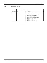
Page 7: ...tion 4 2 3 resistor value changed Section 4 2 4 minor update Section 7 1 2 minor update Section 7 2 resistor value changed Section 11 1 minor update Section 11 2 minor update Section 11 5 minor update 2 6 Loudspeakers Line Isolator System About this manual en 7 Bosch Security Systems B V Installation and Operation Manual 2014 03 V1 1 ...

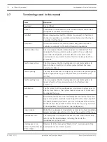
Page 8: ...he Master Unit 90 s Fault reporting time The time required by the Loudspeakers Line Isolator System to report a fault i e time required to go to the fault warning condition Initialization The first state that the Loudspeakers Line Isolator System goes to after system start up The system takes a maximum of 10 seconds to initialize the loop Loop Redundant loudspeaker line All loudspeakers broadcast ...

Page 9: ...egment The wire and or group of loudspeakers between two Isolator Boards and between the Master Unit and an Isolator Board Voice alarm zone Geographical part of an evacuation zone in which an evacuation alarm is carried out Alarm zones are defined per installation Walk Test Test mode for checking the loop by feeding the power and signal from one side of the loop only Zone An area where the same si...

Page 10: ... outputs of the public address voice alarm system are connected to the Master Unit Each Master Unit has connections for six loudspeaker loops Each loudspeaker loop can manage 500 watts A maximum of 50 Isolator Boards can be installed in each loudspeaker loop The front panel on the Master Unit has LEDs to indicate The status of each loop The status of the mains and back up battery power supplies Al...

Page 11: ...heck if the Isolator Board and loudspeaker cable including polarity are correctly connected PM1 LISD Loudspeaker DC Blocking Board Referred to in this manual as DC Blocking Board The DC Blocking Board blocks DC and provides overload protection by current limiting It has the same connections as the Isolator Board which allows for quick and convenient connection of the loudspeaker loop and tap off c...

Page 12: ...ng the Loudspeakers Line Isolator System with these products and product lines make sure you have checked and fulfilled the systems requirements as described in Plena VAS system requirements page 17 and Praesideo system requirements page 18 The Loudspeakers Line Isolator System is compatible for use with the Praesideo family loudspeaker supervision products LBB4440 00 LBB4441 00 LBB4442 00 and LBB...

Page 13: ...r each loudspeaker page 21 2 A branch consisting of one or more loudspeakers is connected to the tap off connection on an Isolator Board In this case a DC Blocking Board must be connected to each loudspeaker maximum 20 watt loudspeaker load If open circuit detection is required for this option the open circuit detection jumper on the Isolator Board should be set to ON and the end of line resistor ...

Page 14: ... reported within the fault reporting time of 90 seconds The yellow LED indicator is lit on the Isolator Board indicating that the adjacent segment has a short circuit Interruption of audio within the fault isolation time Audio returns to the unaffected segments and the loudspeakers connected to the tap offs of the Isolator Boards Loss of audio in the segment with the short circuit After resolution...

Page 15: ...oop every 20 to 40 seconds This can lead to audible glitches in the affected tap off and in rare cases audible glitches in the main loop during the fault condition After resolution of the fault the fault recovery time is 100 seconds Overload Overload threshold can be set per Isolator Board 10 36 or 100 watts When audio is present that exceeds this threshold level the system reports a loop fault wi...

Page 16: ...urity com You have the manufacturer approved materials to install this equipment There is a mains power outlet of sufficient rating close to the intended location of the product s The installation is in a clean dust free environment The ventilation airflow of the 19 unit s is unobstructed The ambient temperature of the 19 unit s is within the operating range 5 ºC to 55 ºC There is sufficient free ...

Page 17: ...o more than one router To ensure correct ground short detection on the Master Unit the ground short slave switch on one connected loop is set to off and the ground short slave on the other loops is set to on Each zone output is connected to one loop input The fault outputs of the Loudspeakers Line Isolator System are connected to the input triggers of the Plena VAS system Each loop fault output ca...

Page 18: ...Praesideo system or fault outputs can be connected in series The general fault output on the master is connected in series with the master loop fault outputs The general fault output is a normally energized fail safe relay The chosen contact inputs are configured as Zone Line fault inputs see also the Praesideo Installation and User Instructions The output contacts of the Loudspeaker Line Isolator...

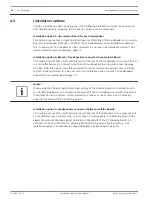
Page 19: ...cable impedance in each loop is 24 ohms Some standards limit the number of loudspeakers that may be lost due to a fault for example 25 loudspeakers Do not install more than the maximum allowed number of loudspeakers in a segment or to the tap off of an Isolator Board The maximum cable length from a tap off to a loudspeaker is 50 m 164 ft independent of the loop length When the Isolator Board is no...

Page 20: ...lus the loop tap off can be monitored for open circuits See Installation option 2 Branch of loudspeakers connected to an Isolator Board page 23 Notice When using the 100 watt permissible load setting of the Isolator Board in combination with the DC Blocking Board an overload on the tap off of the DC Blocking Board will not lead to a fault indication in the system If fault indication is required us...

Page 21: ...n Isolator Board used for each loudspeaker The tap off open circuit detection jumper should be set to ON The tap off short circuit detection jumper should be set to OFF See Isolator Board settings page 43 5 Loudspeaker Loudspeaker directly connected to tap off of the Isolator Board The following table shows how the audio is affected in the system if installation option 1 is chosen Fault condition ...

Page 22: ...aults on the main loop and or tap off Loss of audio between faults including the affected tap offs Audio artifacts may be present between Isolator Boards with the tap off faults 22 en Planning Loudspeakers Line Isolator System 2014 03 V1 1 Installation and Operation Manual Bosch Security Systems B V ...

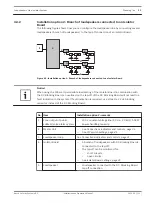
Page 23: ...t indication is required use at least a 22 µF blocking capacitor instead of the DC Blocking Board No Item Installation option 2 remarks 1 Zone output of public address voice alarm system 100 V constant voltage line 50 Hz 20 kHz 500 W power handling capacity 2 Master Unit See Connections indicators and controls page 31 See DIP switch settings page 41 3 Loudspeaker loop See Connections indicators an...

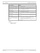
Page 24: ...ap off or when one of the loudspeakers is connected to the Isolator Board at a distance Whether or not a branch should be monitored for open circuits depends on local standards The following table shows how the audio is affected in the system if installation option 2 is chosen Fault condition Impact Open circuit in the main loop No loss of audio Short circuit in the main loop No loss of audio Open...

Page 25: ...lator Boards The tap off open circuit detection jumper on the Isolator Boards should be set to OFF The tap off short circuit detection jumper on the Isolator Boards should be set to OFF see Configuration page 41 5 Loudspeaker Loudspeaker connected to the DC Blocking Board tap off connection According to certain standards a maximum of 25 loudspeakers can be connected between two Isolator Boards 6 D...

Page 26: ...io on the affected DC Blocking Board tap off Short circuit in the DC Blocking Board tap off Loss of audio on the affected DC Blocking Board tap off Two or more faults on the main loop and or DC Blocking Board tap off Loss of audio in the affected segments and or affected DC Blocking Board tap offs Audio artifacts may be present in segments that are isolated See also Configuration page 41 Installat...

Page 27: ...peaker connected to tap off connection of an Isolator Board or DC Blocking Board 6 DC Blocking Board DC Blocking Boards connected to loudspeakers as required 7 Tap off for loudspeakers According to some standards a maximum of 25 loudspeakers can be connected to an Isolator Board tap off or in a segment 8 End of line resistor 47 kohm 0 5 watt resistor connected across the unused loop terminal of th...

Page 28: ... equipment make sure you use applicable antistatic devices as required such as antistatic mats wrist straps and garments Notice The installation of the public address voice alarm system is not described in this manual Refer to the relevant manual for more information Notice Depending on the installation setup and type of loudspeaker either an Isolator Board DC Blocking Board or DC blocking capacit...

Page 29: ...move the applicable punch out holes from the housing as required depending on the type of cables being used 6 mm or 9 mm diameter holes 3 Make sure the all round clearance between the cable and the hole is less than 1 mm This will guarantee the IP30 rating of the housing 4 Use the mounting holes to secure the housing to a solid flat surface loudspeaker or loudspeaker fire dome 5 Inspect the board ...

Page 30: ...VDC and should be connected in series with the loudspeaker The value of this capacitor depends on the load of the loudspeaker and the desired frequency response Typically for a full range speaker 4 7 µF is used for 10 watts 47 µF is used for 100 watts For horns the valve is lower Preferably a DC Blocking Board should be used Notice When using the PRS 4B125 amplifier in combination with the 10 watt...

Page 31: ... by qualified personnel Notice For information on connecting loudspeakers refer to the relevant operation manual or system manual for the loudspeaker For information on the preferred cable type and length that can be used with the Loudspeakers Line Isolator System refer to System Prerequisites page 16 Technical data page 54 6 Loudspeakers Line Isolator System Connections indicators and controls en...

Page 32: ...Loop RTN Loop RTN Loop RTN Loop RTN Loop RTN Disable Loop Gnd Short Slave Walk Test Reserved Disable Loop Gnd Short Slave Walk Test Reserved Disable Loop Gnd Short Slave Walk Test Reserved Disable Loop Gnd Short Slave Walk Test Reserved Disable Loop Gnd Short Slave Walk Test Reserved OK OK OK OK OK OK 1 2 3 4 5 6 7 810 11 12 9 13 100V In Loop 1 Loop Out Loop RTN Loop Fault Ground Short Loop Disabl...

Page 33: ...e loop is disabled NO is closed when a loop fault is detected Note The Loop Fault output contact is not triggered by ground short faults Ground short Pin 4 Common Pin 5 Ground fault NC Pin 6 Ground fault NO NO is open when no ground fault is detected the loop is initializing the loop is disabled NO is closed when a ground short fault is detected 3 Loop OK LED This indication is active in Walk Test...

Page 34: ...kup fault is detected backup supervision is off NO is closed when a backup fault is detected The fault outputs of the Master Unit can be connected to inputs of the public address voice alarm system 7 Mains Battery supervision Switches to enable mains and battery supervision See DIP switch settings page 41 8 Voltage selection Voltage selection switch for 115 230 VAC Use this switch to set the corre...

Page 35: ...ut socket 115 230 VAC 13 Type plate Plate containing information on product type and serial number Loudspeakers Line Isolator System Connections indicators and controls en 35 Bosch Security Systems B V Installation and Operation Manual 2014 03 V1 1 ...

Page 36: ...V 4 3 9 X1 X2 X3 X4 X5 X6 X 7 R207 R208 R 2 0 9 V300 1 1 1 1 1 1 9 10 11 12 3 4 5 6 8 7 No Item Description 1 Tap off power 100 watts X4 Tap off overload threshold is 100 watts 2 Tap off power 36 watts X5 Tap off overload threshold is 36 watts 3 Test button Momentary switch to test the loop connection of the Isolator Board 4 Tap off power 10 watts X6 Tap off overload threshold is 10 watts 5 LED In...

Page 37: ...tion X1 10 X2 100 volt loop connection 2 pin removable screw connector pin designation from left to right Loop connection X2 Loop connection X2 11 X3 100 volt loudspeaker tap off connection 2 pin removable screw connector pin designation from left to right Tap off connection to loudspeaker s X3 Tap off connection to loudspeaker s X3 Warning If there is a short overload on the Isolator Board the po...

Page 38: ... Loop connection X1 Loop connection X1 2 X2 100 volt loop connection 2 pin removable screw connector pin designation from left to right Loop connection X2 Loop connection X2 3 X3 100 volt loudspeaker tap off connection 2 pin removable screw connector pin designation from left to right Tap off connection to loudspeaker s X3 Tap off connection to loudspeaker s X3 6 3 38 en Connections indicators and...

Page 39: ...test button 3 is pressed The polarity is incorrect There is an open circuit or short circuit in the segment The Isolator Board is defective 7 Repeat the above steps for the next segment s Notice If there is a short circuit in the segment the Isolator Board indicator on the previous segment will light up continuously 8 Connect the last segment to the Master Unit loop return connection 1 9 Check the...

Page 40: ...LED indication 3 on the rear panel of the Master Unit 5 If the loop OK LED 3 is on the connection is correct 6 If the loop OK LED 3 does not light up Check the test button 3 and LED indicator 5 on each Isolator Board as described in option A Alternatively turn on the public address voice alarm system and broadcast audio then perform a walk test in the loop to determine at which point the audio sto...

Page 41: ...alk Test Reserved Disable Loop Gnd Short Slave Walk Test Reserved OK OK OK OK OK OK 5 7 810 Voltage ground selection No Item Description 8 Voltage selection Voltage selection switch for 115 230 VAC Use this switch to set the correct mains voltage for your region 10 Ground Lift When ground lift is enabled the technical ground power supply is decoupled from the safety ground chassis See Praesideo sy...

Page 42: ...K LED 3 and Connect Fault LED indication 4 on the rear of Master Unit are inactive Refer to Master Unit rear view page 47 ON Walk Test mode active Loop OK LED 3 and Connect Fault LED indication 4 on rear of Master Unit are active Refer to Master Unit rear view page 47 4 Reserved OFF Reserved ON Reserved 7 1 Mains supervision OFF default Mains fault reporting deactivated LED and fault relay ON Main...

Page 43: ... 4 2 4 V427 V 4 2 8 V3 V4 V6 V 4 3 1 V433 V434 V 4 3 5 V436 V 4 3 7 V 4 3 8 V 4 3 9 X1 X2 X3 X4 X5 X6 X 7 R207 R208 R 2 0 9 V300 1 1 1 1 1 1 12 4 6 8 7 No Jumper Type Description Value Setting 1 2 pin jumper X4 Maximum permissible load 100 W This setting determines the overload detection level Use this setting if the loudspeaker load on the tap off is between 36 watts and 100 watts When the 100 wa...

Page 44: ...tting if the loudspeaker load is 10 watts or less and 20 kHz filter is required Note If a PRS 4B125 amplifier is used a DC Blocking Board or a 33 ohm 3 watt resistor must be used in series with the loudspeaker connected to the tap off of the Isolator Board 7 3 pin jumper X402 Tap off open circuit detection ON default Can be used for installation options 1 or 2 Note For installation option 2 an end...

Page 45: ...ter Unit is supplied with mains power Master Unit is switched off or not supplied with mains or backup power Mains supervision is switched off 3 Backup power Green ON Master Unit is supplied with backup power OFF Master Unit is not supplied with backup power Backup power voltage is below 18 volts 4 Backup fault Yellow ON Backup power voltage is below 21 1 volts and the Master Unit is supplied with...

Page 46: ...dspeaker loop Master Unit loudspeaker loop is initializing Loop is disabled 7 Loop initializing Yellow ON Loudspeaker loop is initializing Time required for loop to build up before a loop fault can be triggered Maximum initialization time 10 seconds after start up OFF Loudspeaker loop initialization finished Loop is disabled 8 Walk Test mode Yellow ON Walk Test is enabled OFF Walk Test is disabled...

Page 47: ...t Slave Walk Test Reserved Disable Loop Gnd Short Slave Walk Test Reserved Disable Loop Gnd Short Slave Walk Test Reserved Disable Loop Gnd Short Slave Walk Test Reserved Disable Loop Gnd Short Slave Walk Test Reserved OK OK OK OK OK OK 3 4 The following indicators are active when the loop is enabled and the Master Unit is in walk test mode No Description Color LED status System status 3 Loop OK G...

Page 48: ... will display a continuous loop fault until the loop is installed correctly When the loop is installed correctly the connection fault LED 4 on the rear panel of the Master Unit will switch off within the fault recovery time The loop OK LED 3 on the rear panel of the Master Unit will light up immediately Walk test procedure 1 Make sure the Master Unit is switched on 2 Set the loop to Walk Test mode...

Page 49: ...version HW 04 15 or higher Plena Ground short slave switches of the Master Unit are incorrectly set when used with a Plena system An amplifier is used on more than one router More than one router is connected to the Master Unit There is a ground short in one of the loops Set one ground short slave switch to OFF the rest to ON Connect two amplifiers exclusively to a router Connect one router or con...

Page 50: ...or System indicates fault only during audio broadcasting Installation option 1 There is an overload on an Isolator Board tap off Check load on the Isolator Board Check for short circuits Intermittent audio in a loop Installation option 3 Short circuit after DC decoupling in a segment when not using a DC Blocking Board or a 33 ohm resistor and decoupling capacitor in series with a loudspeaker Use a...

Page 51: ...ettings and connections are OK Check with another Isolator Board Check with known good loudspeaker No audio from a speaker or branch Installation option 2 Loudspeaker load exceeds maximum permissible load setting End of line is not sensed by Isolator Board Isolator Board is defective Loudspeaker is defective DC Blocking Board or 33 ohm resistor with DC blocking capacitor not installed for PRS 4B12...

Page 52: ...Use the Walk Test mode to locate the problem Check the affected tap off for short circuit or overload Check the overload settings on the Isolator Board Intermittent audio on a tap off and or segment Installation option 1 and 2 There are two or more faults in a loop Artifacts may be heard in the loop between the first and last fault including tap offs The system will retry the loop every 15 to 35 s...

Page 53: ...t of the internal fans Once a year you should use a vacuum cleaner to clean the air inlets of all units in the 19 inch racks Check the connectors and grounding Check all connections for wear or damage Make sure all screw terminals and ground PE connections are fully tightened Perform a Walk Test Regularly perform a Walk Test according to local regulation or contractual obligations See Walk Test pa...

Page 54: ...ut loop 1 6 Floating contacts 24 V 1 A Fault relays except general fault relay OK state is normally de energized NO is open General fault relay OK state is Failsafe normally energized NC is open failsafe Performance Max number of Isolator Boards in loop 50 Power handling capacity per loop 500 W Frequency range 50 Hz 20 kHz Max sum blocking capacitance Max sum blocking capacitance per loop 4700 µF ...

Page 55: ...rcuit detection 10 Ω detected on primary output and return Fault isolation time 50 Isolator Boards or less per loop 4 s Ground short 50 kohm Figure 11 1 Battery power consumption 24 Vdc Loudspeakers Line Isolator System Technical data en 55 Bosch Security Systems B V Installation and Operation Manual 2014 03 V1 1 ...

Page 56: ...ckets 360 mm 14 2 in Weight 15 9 kg 35 05 lb Mounting 19 rack Color Charcoal with silver Environmental Operating temperature 5 ºC to 55 ºC 23 ºF to 131 ºF Storage temperature 20 ºC to 70 ºC 4 ºF to 158 ºF Relative humidity 15 to 90 Air pressure 600 to 1100 hPa 56 en Technical data Loudspeakers Line Isolator System 2014 03 V1 1 Installation and Operation Manual Bosch Security Systems B V ...

Page 57: ... housing an optional mounting bracket LBB 4446 00 is required Weight Approx 180 g 6 3 ounces Color Red Fire resistant properties UL60065 Ingres protection IP30 Punch out holes for cables 3 holes for 6 mm wires 3 holes for 9 mm wires Environmental Operating temperature 5 ºC to 55 ºC 23 ºF to 131 ºF Storage temperature 20 ºC to 70 ºC 4 ºF to 158 ºF Relative humidity 15 to 90 Air pressure 600 to 1100...

Page 58: ...rox 16 g 0 6 ounces Environmental Operating temperature 5 ºC to 55 ºC 23 ºF to 131 ºF Storage temperature 20 ºC to 70 ºC 4 ºF to 158 ºF Relative humidity 15 to 90 Air pressure 600 to 1100 hPa Approvals Safety acc to EN 60065 Emission acc to EN 55103 1 Immunity acc to EN 55103 2 and EN 50130 4 Maritime acc to EN 60945 Evacuation acc to EN 54 16 Compliance Compliant for use as described in NEN2575 V...

Page 59: ......

Page 60: ...Bosch Security Systems B V Torenallee 49 5617 BA Eindhoven The Netherlands www boschsecurity com Bosch Security Systems B V 2014 ...

Reviews: