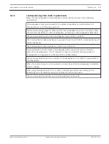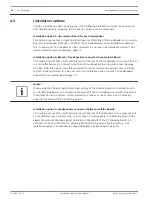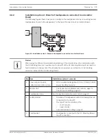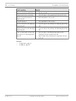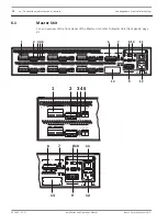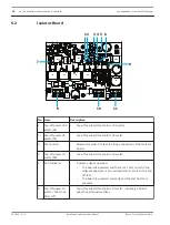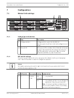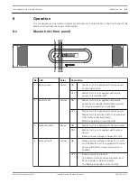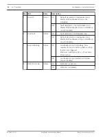
No. Item
Description
1
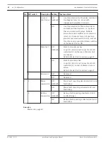
100 volt audio I/O
–
6-pin removable screw connector (pin designation from left to
right):
–
100 V In:
–
Pin 1: +100 V audio in from zone output of public
address/voice alarm system.
–
Pin 2: -100 V audio in from zone output of public
address/voice alarm system.
–
Loop Out:
–
Pin 3: +100 V primary output to loudspeaker loop.
–
Pin 4: -100 V primary output to loudspeaker loop.
–
Loop RTN:
–
Pin 5: +100 V return from loudspeaker loop.
–
Pin 6: -100 V return from loudspeaker loop.
2
Loop fault outputs –
6-pin removable screw connector (pin designation from left to
right):
–
Loop fault:
–
Pin 1: Common.
–
Pin 2: Loop fault (NC).
–
Pin 3: Loop fault (NO).
–
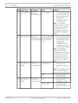
NO is open when:
–
no loop fault is detected.
–
the loop is initializing.
–
the loop is disabled.
–
NO is closed when a loop fault is detected.
Note: The Loop Fault output contact is not triggered by ground
short faults.
–
Ground short:
–
Pin 4: Common.
–
Pin 5: Ground fault (NC).
–
Pin 6: Ground fault (NO).
–
NO is open when:
–
no ground fault is detected.
–
the loop is initializing.
–
the loop is disabled.
–
NO is closed when a ground short fault is detected.
3
Loop OK LED
–
This indication is active in Walk Test mode. During Walk Test
mode, this indicator lights up when the loop is OK.
–
See Master Unit indicators Master Unit (rear view), page 47.
4
Connection fault
LED
–
This indication is active in Walk Test mode. This indicator
lights up when the last segment is connected in reverse
polarity.
–
See Master Unit indicators Master Unit (rear view), page 47.
Loudspeakers Line Isolator System
Connections indicators and controls | en
33
Bosch Security Systems B.V.
Installation and Operation Manual
2014.03 | V1.1 |

