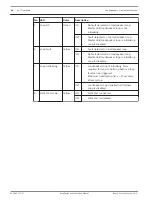
No. Item
Description
5
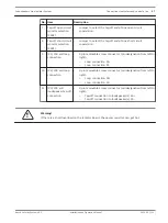
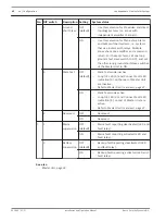
DIP switches
–
Switches to select:
–
Disable loop.
–
Ground short slave setting.
–
Walk Test mode.
–
See DIP switch settings, page 41.
6
Common fault
outputs
–
9-pin removable screw connector (pin designation from left to
right):
–
General (fail-safe output contact):
–
Pin 1: Common.
–
Pin 2: General fault (NC).
–
Pin 3: General fault (NO).
–
NC is open when no loop or ground short fault is detected.
–
NC is closed when a loop or ground short fault is detected.
–
Mains:
–
Pin 4: Common.
–
Pin 5: Mains fault (NC).
–
Pin 6: Mains fault (NO).
–
NO is open when:
–
no mains fault is detected.
–
mains supervision is off.
–
NO is closed when a mains fault is detected.
–
Battery:
–
Pin 7: Common.
–
Pin 8: Backup fault (NC).
–
Pin 9: Backup fault (NO).
–
NO is open when:
–
no backup fault is detected.
–
backup supervision is off.
–
NO is closed when a backup fault is detected.
–
The fault outputs of the Master Unit can be connected to
inputs of the public address/voice alarm system.
7
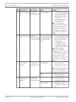
Mains/ Battery
supervision
–
Switches to enable mains and battery supervision.
–
See DIP switch settings, page 41.
8
Voltage selection
–
Voltage selection switch for 115/230 VAC.
–
Use this switch to set the correct mains voltage for your
region.
9
+24-48 VDC inlet
–
DC back-up supply input connector 24-48 VDC (5A).
10 Ground Lift
–
When ground lift is enabled, the technical ground (power
supply) is decoupled from the safety ground (chassis).
–
See Praesideo system requirements, page 18 and the Praesideo
Installation and User Instructions.
11 Power on/off
–
AC mains power switch.
34
en | Connections indicators and controls
Loudspeakers Line Isolator System
2014.03 | V1.1 |
Installation and Operation Manual
Bosch Security Systems B.V.

