Configuration
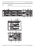
Master Unit settings
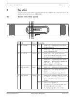
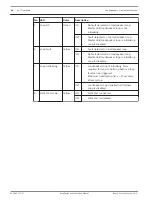
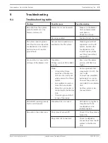
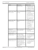
115:
100-120V
50-60Hz
230:
220-240V
50-60Hz
T6.3A 250V
T6.3A 250V
115/230V
Mains
Grounded
Floating
Battery 24 / 48 V
4.5 A Max
Non-isolated input
0
+
Caution
Risk of electric shock.
Do not open
Avis
Risque de choc electrique.
Ne pas ouvrir
100V In
Loop 1
Loop Out
Loop RTN
+ – + – + –
Loop Fault Ground Short
Loop
Disable Loop
Gnd Short Slave
Walk Test
Connect
Fault
Mains
Battery
Fault Outputs
General
Mains
Battery
Reserved
Supervision
Ground Lift
100V In
Loop 6
Loop Out
+ – + – + –
Loop Fault Ground Short
Loop
Connect
Fault
100V In
Loop 2
Loop Out
+ – + – + –
Loop Fault Ground Short
Loop
Connect
Fault
100V In
Loop 3
Loop Out
+ – + – + –
Loop Fault Ground Short
Loop
Connect
Fault
100V In
Loop 4
Loop Out
+ – + – + –
Loop Fault Ground Short
Loop
Connect
Fault
100V In
Loop 5
Loop Out
+ – + – + –
Loop Fault Ground Short
Loop
Connect
Fault
Loop RTN
Loop RTN
Loop RTN
Loop RTN
Loop RTN
Disable Loop
Gnd Sho
rt Slave
Walk
Test
Reserved
Disable Loop
Gnd Short Slave
Walk Test
Reserved
Disable Loop
Gnd Sho
rt Slave
Walk
Test
Reserved
Disable Loop
Gnd Sho
rt Slave
Walk
Test
Reserved
Disable Loop
Gnd Short Slave
Walk Test
Reserved
OK
OK
OK
OK
OK
OK
5
7
8 10
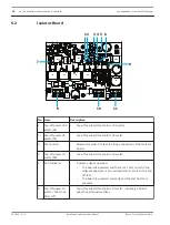
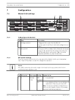
Voltage/ground selection
No. Item
Description
8
Voltage selection
Voltage selection switch for 115/230 VAC.
Use this switch to set the correct mains voltage for your
region.
10 Ground Lift
When ground lift is enabled, the technical ground (power
supply) is decoupled from the safety ground (chassis).
See Praesideo system requirements, page 18, and the
Praesideo Installation and User Instructions.
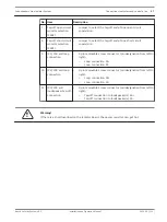
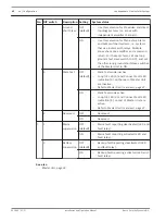
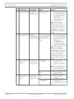
DIP switch settings
There is a 2‑way DIP switch (5) on the rear panel of the Master Unit for each loudspeaker
loop. These DIP switches are used for configuration purposes.
Notice!
DIP switch numbering is from left to right. A DIP switch in the up position is OFF; A DIP
switch in the down position is ON.
No. DIP switch
Description Setting
System status
5
1
Disable
Loop
OFF
(default)
–
Loop enabled.
ON
–
Loop disabled. When a loop is disabled, all
indications of that loop are turned off.
Note: If no loop is enabled, all indications on
the front of the Master Unit are off, including
the mains and backup indication.
7
7.1
7.1.1
7.1.2
Loudspeakers Line Isolator System
Configuration | en
41
Bosch Security Systems B.V.
Installation and Operation Manual
2014.03 | V1.1 |


