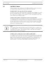
Installation option 1: One Isolator Board for each loudspeaker
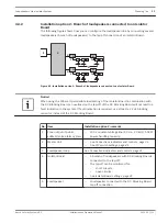
The following figure shows how you can configure the loudspeaker line by using an Isolator
Board for each loudspeaker:
1
2
3
4
5
5
4
4
4
4
4
3
Figure 4.1: Installation option 1: One Isolator Board for each loudspeaker
No. Item
Installation option 1: remarks
1
Zone output of public
address/voice alarm system
–
100 V constant voltage line (50 Hz – 20 kHz), 500 W
power handling capacity.
2
Master Unit
–
See Connections indicators and controls, page 31.
–
See DIP switch settings, page 41.
3
Loudspeaker loop
–
See Connections indicators and controls, page 31.
4
Isolator Board
–
An Isolator Board used for each loudspeaker:
–
The tap-off open circuit detection jumper should
be set to ON.
–
The tap-off short circuit detection jumper should
be set to OFF.
–
See Isolator Board settings, page 43.
5
Loudspeaker
–
Loudspeaker directly connected to tap-off of the
Isolator Board.
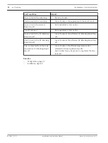
The following table shows how the audio is affected in the system if installation option 1 is
chosen:
Fault condition
Impact
Open circuit in the main loop
–
No loss of audio.
Open circuit in the tap-off
–
Only affects the loudspeaker that has a fault.
Short circuit in the main loop
–
No loss of audio.
Short circuit in the tap-off
–
Not applicable for this installation option. Short
circuits are handled as overloads.
4.3.1
Loudspeakers Line Isolator System
Planning | en
21
Bosch Security Systems B.V.
Installation and Operation Manual
2014.03 | V1.1 |

