40
en | Installation wiring
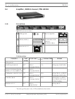
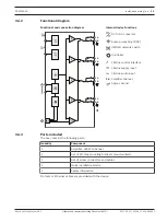
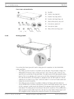
PRAESENSA
2021.12.21 | V0.15b | F.01U.402.882
Underwriters Laboratories Listing Document (ULLD)
Bosch Security Systems B.V.
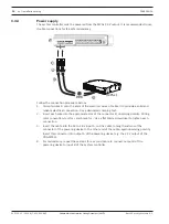
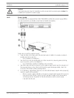
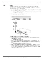
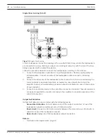
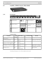
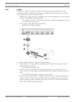
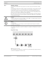
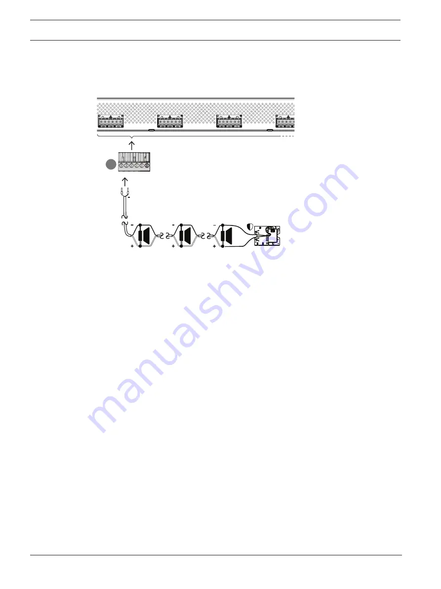
Three different loudspeaker connection topologies are supported, configurable in the system
configuration:
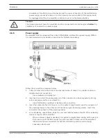
Single Class B wiring
D
(EOL-US)
+
Figure 3.3:
Single Class B wiring
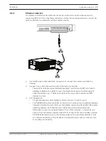
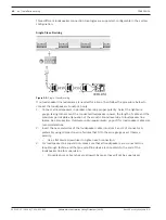
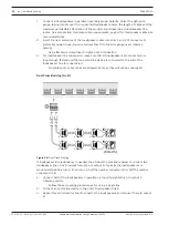
If no loudspeaker line redundancy is needed for a zone, then follow the procedure below to
connect the loudspeakers to output A only:
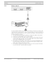
1.
Connect all loudspeakers in parallel, observing proper polarity. Select the right wire
gauge, taking into account the connected loudspeaker power, the length of cable and the
maximum permissible attenuation of the acoustic sound level due to loudspeaker line
losses. See also section
Field wire cable requirements, page 19 for loudspeaker cable size
recommendations.
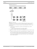
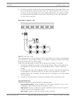
2.
Insert the near end wires of the loudspeaker cable into slots 1 and 2 of connector D,
preferably using crimped on wire ferrules that fit to the wire gauge used. Observe
polarity.
–
Use a flat blade screwdriver to tighten each connection.
3.
For loudspeaker line supervision, make sure that all loudspeakers are connected in a
loop‑through fashion and that an end‑of‑line device is connected to the end of the
loudspeaker line for supervision.
–
No cable spurs or branches are allowed, because they will not be supervised.


