background image

PRAESENSA

From installation to configuration | en

47

Bosch Security Systems B.V.

Installation manual

2019.11 | V1.00 |

6

From installation to configuration

To configure the system, an Ethernet connection is required between the configuration PC and
the system controller. Then access the device’s webserver through its URL using a browser.
For general and detailed system configuration instructions, see the PRAESENSA configuration
manual.

6.1

MAC-addresses and hostname

All OMNEO connected PRAESENSA devices use one or two MAC‑addresses and have a device
hostname; the system controller also has a control hostname to get access to its webserver.
The MAC‑addresses are in the Bosch Security Systems vendor range 00:1c:44:xx:xx:xx


or in

the Audinate vendor range 00:1d:c1:xx:xx:xx. In many corporate networks the MAC‑addresses
of networked devices need to be entered in a table in the DHCP‑server, to allow access. For
that purpose the MAC‑addresses of each PRAESENSA device are printed on the product label:

The system controller has two MAC‑addresses and two hostnames. The device
MAC‑address and the Control MAC‑address (C‑MAC) are both in the Bosch Security
Systems vendor range. The device hostname, of for example the PRA-SCL, is derived from
the MAC‑address: PRASCL-xxxxxx.local, with xxxxxx being the last 6 hexadecimal digits (3
octets) of the MAC‑address. The domain name label ‘local’ is used as a pseudo-top-level
domain for hostnames in local area networks that can be resolved via the Multicast DNS
name resolution protocol. It is possible to ping a system controller via this name (for
example: PRASCL-xxxxxx.local. The system composition webpage does not show
the .local extension; this is implicit. The control hostname is the same as the device
hostname, but with a postfix -ctrl. So, it becomes for example: PRASCL-xxxxxx-ctrl.local.
To get access to the webserver, of for example, the PRA-SCL, this address is used as URL
(Uniform Resource Locator). This address is also used for the Open Interface.

The PRA-AD604 and PRA-AD608 only have a MAC‑address in the Bosch Security Systems
vendor range. Their hostname is PRAAD604-xxxxxx.local


or PRAAD608-xxxxxx.local.

The PRA-MPS3 only has a MAC‑address in the Audinate vendor range. The hostname is:
PRAMPS3-xxxxxx.local.

The PRA-CSLD and PRA-CSLW have two MAC‑addresses, but only one hostname. Its
device MAC‑address in the Audinate vendor range and its C‑MAC address is in the Bosch
Security Systems vendor range. The device hostname is derived from the device
MAC‑address: PRACSLD-xxxxxx.local


or PRACSLW-xxxxxx.local.

The PRA-CSE and PRA-EOL do not have a MAC‑address, nor hostname.

Remarks:

The program OMNEO Control only shows device hostnames, not the control hostname of
a system controller.

The configuration webpages show device hostnames without .local domain extension. It
does not show control hostnames, neither the one of its own web server, nor from other
system controllers.

Both MAC‑addresses of the system controller and call station are on the same printed
circuit board (PCB), so in case of PCB exchange both MAC‑addresses will change and
also the derived host name(s).

The Firmware upload tool (FWUT) addresses the devices via their device hostname.

The configuration of all devices is described in the PRAESENSA configuration manual.

Summary of Contents for PRAESENSA

Page 1: ...PRAESENSA Public Address and Voice Alarm System en Installation manual ...

Page 2: ......

Page 3: ...cts 20 4 3 Equipment racks and cabinets 20 4 4 Mounting the 19 rack devices 20 4 5 Cable requirements 22 4 5 1 Precautions 22 4 5 2 Cable type recommendations 23 4 6 Network requirements and considerations 25 4 6 1 Network topology 26 4 6 2 Network connector ports 26 4 6 3 Audio content and device control 26 4 6 4 Network security 26 4 6 5 Network speed and bandwidth usage 27 4 6 6 System size lim...

Page 4: ... 6 1 Parts included 56 7 6 2 Memory card 57 7 6 3 Power supply 58 7 6 4 Ethernet network 59 7 6 5 Internal battery 60 7 6 6 Reset to factory default 60 7 7 Approvals 61 7 8 Technical data 61 8 Amplifier 600W 4 channel PRA AD604 64 8 1 Introduction 64 8 2 Functions 64 8 3 Functional diagram 66 8 4 Indicators and connections 67 8 5 Installation 68 8 5 1 Parts included 68 8 5 2 Safety ground 69 8 5 3...

Page 5: ...nnections 107 11 5 Installation 108 11 5 1 Parts included 108 11 5 2 Battery and fuse 109 11 5 3 Mains power connection 115 11 5 4 Amplifier power supply 116 11 5 5 Lifeline 117 11 5 6 Power supply connection to system controller 119 11 5 7 Power over Ethernet 120 11 5 8 Ethernet network 121 11 5 9 Control inputs 123 11 5 10 Control outputs 124 11 5 11 Reset to factory default 125 11 6 Approvals 1...

Page 6: ...agram 154 14 4 Indicators and connections 155 14 5 Installation 156 14 5 1 Parts included 156 14 5 2 Power supply connection 157 14 5 3 Fault relay connection 157 14 6 Approvals 157 14 7 Technical data 158 15 Fiber transceiver PRA SFPLX PRA SFPSX 161 15 1 Introduction 161 15 2 Functions 161 15 3 Functional diagram 161 15 4 Installation 162 15 4 1 Parts included 162 15 4 2 Application 162 15 4 3 Tr...

Page 7: ... Compatibility with other network data 175 17 4 Static IP binding 175 18 Troubleshooting 179 19 Maintenance and service 181 19 1 Preventive maintenance 181 19 2 Corrective maintenance 182 19 3 Device replacement 182 19 3 1 System controller 182 19 3 2 Amplifier 183 19 3 3 Multifunction power supply 184 19 3 4 Call station 185 20 EN 54 16 EN 54 4 compliance 186 20 1 Introduction 186 20 2 Checklist ...

Page 8: ...oid injury from tip over 7 The system shall not be installed near water or heat sources 8 System power supplies shall be connected to a mains power outlet socket with a protective earthing connection An external readily operable mains plug or all pole mains switch shall be installed 9 Only replace a power supply mains fuse with a fuse of the same type 10 The chassis ground screw of an amplifier sh...

Page 9: ...has been tested and found to comply with the limits for a Class A digital device pursuant to Part 15 of the FCC and Canadian ICES 003 requirements These limits are designed to provide reasonable protection against harmful interference when the equipment is operated in a commercial environment This equipment generates uses and can radiate radio frequency energy and if not installed and used in acco...

Page 10: ...a high level introduction description of the PRAESENSA Public Address and Voice Alarm System A brief product description and overview is included Chapter 4 General installation procedures and instructions page 18 describes considerations for rack building cable selection and network design Chapter 5 System composition page 33 describes considerations and methods for system composition battery calc...

Page 11: ... integrator Operator Quick installation guide QIG Basic step by step installations instructions X Installation manual Detailed system and product descriptions and installation instructions X X Configuration manual Detailed instructions for configuration diagnosis and operation X X X Notice Retain all documentation supplied with the products for future reference Visit www boschsecurity com PRAESENS...

Page 12: ...sch be held liable for any special direct indirect or consequential damages or any other damages whatsoever resulting from any use or distribution of this list 2 5 Copyright notice Unless otherwise indicated this publication is the copyright of Bosch Security Systems B V All rights are reserved 2 6 Trademarks Throughout this document trademark names may have been used Rather than put a trademark s...

Page 13: ...s to an office with background music in the reception area and some occasional calls as well as to an international airport with many simultaneous automated announcements for flight information and carefully selected music programs in lounges restaurants and bars In all cases it can be installed to operate also as a certified voice alarm system for mass notification and evacuation System functions...

Page 14: ... CSLD LCD call station PRA CSLD PRA CSLW page 130 PRA CSLW LCD call station PRA CSLD PRA CSLW page 130 PRA CSE Call station extension PRA CSE page 143 PRA ES8P2S Ethernet switch PRA ES8P2S page 153 PRA SFPSX and PRA SFPLX Fiber transceiver PRA SFPLX PRA SFPSX page 161 PRA PSM24 and PRA PSM48 Power supply module PRA PSM24 PRA PSM48 page 166 ...

Page 15: ... Each channel serves a separate zone or part of a zone The total amount of output power is defined by the redundant power supply and the heatsink and because both are shared between the amplifier channels it doesn t matter how many loudspeakers are connected to each channel as long as the total combined load does not exceed the maximum of 600 W for the whole amplifier and a load 300 W is not conne...

Page 16: ...e actual status of that zone After starting a call the screen shows the operator the progress of the call indicating when to speak after a start tone or automatic introduction message has finished and showing whether the call was successfully completed in all destinations Fully featured as standard PRAESENSA is an advanced system for Public Address and Voice Alarm purposes The system consists of a...

Page 17: ...gle 12 V battery based backup power facilitating easy system decentralization Amplifiers can be placed closer to the loudspeakers reducing loudspeaker cabling costs which is especially advantageous in case of expensive fire resistant loudspeaker cables DSP power is available in all call stations and amplifiers so DSP power grows with every device added to the system Every zone has its own amplifie...

Page 18: ... the standards compliance of the PRAESENSA VACIE is not compromised the PRAESENSA devices the interconnections to the Fire Detection System network infrastructure loudspeakers and loudspeaker wiring must be installed in accordance with the provisions of applicable standards and the directions provided in this Bosch PRAESENSA installation manual The Bosch PRAESENSA VACIE must be installed and commi...

Page 19: ...nt and authorized Restricted by a special procedure differing from that for access level 2 such as Configuration program with password protection System is mounted in a 19 rack with lockable doors Level 4 Level 3 operations System repair Perform firmware alterations thereby changing the basic mode of operation Persons with specific responsibility for system repair competent and authorized by the m...

Page 20: ...ackaging is the safest container in which to transport products and can also be used to return products for service if necessary 4 3 Equipment racks and cabinets All PRAESENSA equipment housings are of robust construction and meet at least classification IP30 of EN60529 1992 as amended by EN60529 1991 A1 2000 Racks with a swing frame give better access to wiring Racks without rear stands provide m...

Page 21: ...he installation depth Sliding feet prevent making scratches on the surface the device is positioned on Product labels are on the side or rear of each device Notice Make pictures of the product labels and make sure the hostnames and MAC addresses are readable or make a list of all hostnames and MAC addresses of the devices before mounting them in the rack This information is needed for configuratio...

Page 22: ...s but may improve immunity to electrostatic discharges ESD for all devices 4 5 Cable requirements To ensure safety and system reliability different types of cabling are required for cabling inside the racks that house PRAESENSA devices and for cabling between racks and to ancillary items such as loudspeakers 4 5 1 Precautions Prior to installation Confirm the following The cable selected is proper...

Page 23: ...the actual load power and cable length to the next number in the table Copper clad aluminum CCA wires are cheaper but have a higher resistance than copper for the same diameter When using CCA cables take the next bigger wire size from the table Examples A 150 W loudspeaker load on a loudspeaker line of 480 m in a 100 V system Round up to table values 200 W and 500 m This requires 1 5 mm2 copper wi...

Page 24: ...0 5 0 5 0 5 0 75 1 1 5 1 5 2 5 100 328 0 5 0 5 0 5 0 5 0 5 0 75 0 75 1 1 5 50 164 0 5 0 5 0 5 0 5 0 5 0 5 0 5 0 5 0 75 W 100 V 20 50 100 200 300 400 500 600 W 70 V 10 25 50 100 150 200 250 300 400 Loudspeaker power at end of line Ethernet copper cable Notice In order to comply with the strict rules regarding compliance to high energy voltage surges on the Ethernet connections it is mandatory to us...

Page 25: ...iber must not exceed the maximum as specified for the SFP transceiver also considering the fiber diameter Keep all food and beverages out of the work area If fiber particles are ingested they can cause internal hemorrhaging Wear disposable aprons to minimize fiber particles on your clothing Fiber particles on your clothing can later get into food drinks and or be ingested by other means Always wea...

Page 26: ... a midspan PoE power adapter 4 6 3 Audio content and device control PRAESENSA uses OMNEO network technology OMNEO is an architectural approach to connecting devices that need to exchange information such as audio content or device control Built upon multiple technologies including IP and open public standards OMNEO supports the technologies of today such as Audinate s Dante while adopting the stan...

Page 27: ...and receiver The key is volatilely stored on the device and is lost after a power cycle so it must be redistributed via a secure control connection A random key is defined every time an audio connection is created so each audio link has a different key Other security measures in PRAESENSA are The system controller stores passwords and exchanges passwords with the Open Interface API clients using t...

Page 28: ...PRAESENSA network can be expanded easily by inserting more devices in the loop or chain Not all Ethernet switches can be used for PRAESENSA or any other system that is based on Audio over IP As part of the PRAESENSA product range a pre configured managed multi port Ethernet switch is available for more connection flexibility This switch is also included in the PRAESENSA certification for EN54 16 a...

Page 29: ...en using daisy chained devices this will be a problem 4 6 8 Setting up connections The PRAESENSA system controller manages all dynamic OMNEO channels between PRAESENSA devices The software program OMNEO Control is not needed to set up OMNEO channels To set up static Dante channels from Dante sources to the PRAESENSA system controller use Dante Controller from Audinate These static channels will be...

Page 30: ...cal addressing can be recognized by an IP address within the range of 169 254 0 0 16 169 254 0 1 169 254 255 254 with subnet mask 255 255 0 0 Do not use 255 255 255 0 as subnet mask This Link Local addressing is also known as Automatic Private IP Addressing APIPA addressing The Link Local addressing scheme manages fixed IP addresses in the same range as the devices automatically check availability...

Page 31: ... to the system remove the DHCP server and switch the system on again Caution When part of a PRAESENSA system is powered down including the DHCP server while the rest of the system remains in operation then upon restart of the DHCP server some DHCP servers may assign an IP address to a restarting PRAESENSA device that is already in use by one of the devices in operation This will result in unexpect...

Page 32: ...MP for management Without IGMP multicast traffic behaves as broadcast traffic 1 2 2 2 1 Sender 2 Receiver Although OMNEO supports unicast and multicast for audio streams PRAESENSA uses multicast transmission for all dynamic OMNEO audio channels An audio stream of a call station can be received by multiple amplifiers to play out in connected zones Even during an announcement it is possible to add z...

Page 33: ...tems rest of the world A 100 V amplifier is capable of delivering 100 VRMS sine wave power equal to 282 Vpeak to peak before clipping A 100 V loudspeaker is designed to deliver its specified maximum output level with a 100 V input signal A 30 W loudspeaker takes 30 W at 100 V and a 6 W loudspeaker takes 6 W at 100 V Now all loudspeakers belonging to the same group can simply be connected in parall...

Page 34: ...nd 150 W then a mix of PRA AD604 and PRA AD608 amplifiers is needed To determine quickly the minimum amount and type of amplifiers that are needed for a project use the following rules 1 Check how many locations are needed for equipment clusters to be installed technical rooms System decentralization into clusters is often needed because of the size of the area that needs to be covered by the syst...

Page 35: ...e 8 To know what type of amplifiers is needed it is important to consider the average number of channels per amplifier that is needed for this cluster When it is 4 then the cluster can use 4 channel amplifiers all over When it is 8 then all amplifiers must be 8 channel When it is between 4 and 8 channels per amplifier a mix of both models is needed based on interpolation Example Cluster A needs 52...

Page 36: ... loud fragments are not disturbingly loud It is sufficient that an amplifier can drive its loudspeaker load to the maximum level only during peaks its long term average power capability can be much lower It is generally accepted that a continuous output power of 1 8 of the maximum sinewave power is sufficient for most types of music and speech The PRA AD604 and PRA AD608 amplifiers have more margi...

Page 37: ...ns of amplifiers will contain many PRA MPS3 devices each having its own battery This means that the required capacity of each battery must be calculated separately for the PRA MPS3 it is connected to taking the load into account that is served by this specific PRA MPS3 For the devices that are powered from a PRA MPS3 it is important to notice that the power consumption of each device may vary depe...

Page 38: ... audio signal is present for one or more of the audio channels then the power supply voltage increases to the normal operating voltage to be able to drive loudspeaker lines up to 100 VRMS This increases the idle losses in the amplifier channels Of course when the amplifier provides full output power to the loudspeakers the power consumption increases significantly Full output power means a continu...

Page 39: ...be for amplifiers in sleep snooze mode to save power It is also essential that the 48 V for the switch is not disabled at any time In case of mains failure the switch will be powered from the battery connected to the multifunction power supply The power consumption of the switch is highly dependent on the number of ports that are in use and whether these ports provide PoE power to connected device...

Page 40: ... 0 1 1 5 0 42 0 05 0 01 0 12 PRA AD604 Amplifier sleep Amplifier snooze Amplifier active idle Amplifier active low power Amplifier active full power per active RJ45 port 6 0 8 0 32 52 220 0 4 6 0 8 5 39 64 250 0 4 0 50 0 71 3 25 5 33 20 83 0 03 PRA AD608 Amplifier sleep Amplifier snooze Amplifier active idle Amplifier active low power Amplifier active full power per active RJ45 port 6 0 8 4 38 70 ...

Page 41: ...tem controller per active RJ45 port 2 0 35 2 x 0 04 24 24 0 5 0 5 8 58 1 96 PRA CSLD Call station per active RJ45 port 2 per extension PRA CSE 3 with alarm option 0 42 2 x 0 05 3 x 0 01 0 12 24 24 24 24 0 5 0 5 0 5 0 5 10 29 2 45 0 73 2 94 PRA AD604 Amplifier sleep Amplifier snooze Amplifier active idle Amplifier active low power Amplifier active full power per active RJ45 port 2 0 50 0 71 3 25 5 ...

Page 42: ...alarm mode the discharge current can be up to ten times higher than the nominal discharge current and the effective battery capacity then reduces to 75 of the nominal capacity The consequence of this is that the required nominal battery capacity should be around 20 higher than calculated without taking Peukert s law into account Because another 10 additional battery capacity is needed to compensat...

Page 43: ...ied solutions In this case the system controller PRA SCL and Ethernet switch PRA ES8P2S can be powered from a PRA PSM48 power supply module The PRA CSLD and PRA CSLW can be powered via PoE from the PRA ES8P2S The amplifiers PRA AD604 and PRA AD608 can also be powered from a PRA PSM48 not more than one amplifier per power supply Also with this setup it is possible to have battery backup power by us...

Page 44: ...ost of the UPS capacity is needed to keep the system alive during the 24 h in quiescent mode the energy consumption during the much shorter alarm mode is less If this system would use the PRA MPS3 multifunction power supply the amplifiers would be able to run in snooze mode during these 24 h and the total energy consumption and associated battery size would be much lower This system requires a UPS...

Page 45: ...To be able to calculate the required cooling capacity of a cooling system for a technical room with equipment to stay within temperature limits of the equipment the heat production must be known and the maximum ambient temperature that the equipment is allowed to operate in The maximum ambient operating temperature of PRAESENSA rack mounted devices is 50 C 122 F The generated heat is the energy th...

Page 46: ... snooze mode on average resulting in less heat The table below then shows the heat loss related data for the amplifiers in different operating modes Device Mode Dissipated power W Heat loss kJ h Heat loss BTU h Heat loss kcal h PRA AD604 Amplifier active idle Amplifier active low power Amplifier active full power 39 64 100 140 230 360 133 218 341 34 55 86 PRA AD608 Amplifier active idle Amplifier ...

Page 47: ...e to ping a system controller via this name for example PRASCL xxxxxx local The system composition webpage does not show the local extension this is implicit The control hostname is the same as the device hostname but with a postfix ctrl So it becomes for example PRASCL xxxxxx ctrl local To get access to the webserver of for example the PRA SCL this address is used as URL Uniform Resource Locator ...

Page 48: ...Local addressing for the PC Then this must be done manually For Windows 10 the procedure is as follows Click Internet settings in the taskbar then go to Network Internet settings Select Wi Fi and switch off Wi Fi Select Ethernet then go to Change adapter options Double click Ethernet and select Properties Check Internet Protocol Version 4 TCP IPv4 then select Properties Select Use the following IP...

Page 49: ...ltifunction power supply Another amplifier can be connected to the first amplifier and so on For every three amplifiers a multifunction power supply is needed which has a multi port switch built in So the connection possibilities grow with the system size Not all devices need to be looped through in a single long string of devices but parallel paths branches of shorter strings are possible The use...

Page 50: ...or hop counting is the network path between the root the system controller and any possible end point via the shortest path This is important because there is maximum to the number of hops that are allowed for proper communication This has to do with the latency that occurs in every hop and every connection There is a limit of 22 hops Devices that are connected after the 22nd hop are lost in the s...

Page 51: ...e is in identification mode during configuration Yellow LED to show that a device fault is present This may be convenient during installation and servicing Reset Device reset to factory default Button A pinhole gives access to the hidden reset switch This switch resets the device to its factory default settings It clears the OMNEO pre shared key PSK for secure connections and clears the complete l...

Page 52: ...vate this function 1 Use a pin or toothpick to press and hold the reset button for more than 10 s After 10 s the LEDs of the device start flashing 2 Release the reset button and the device will be reset to the factory default setting Indicator test The reset switch can also be used to do an indicator test for this device To activate this function 1 Use a pin or toothpick to press the reset button ...

Page 53: ...ation using a browser 7 2 Functions System control and audio routing Capability to control a system with up to 250 devices serving more than 500 zones Native support for switched single subnet networks with add on support for routed multi subnet topologies Dynamic allocation of multiple and simultaneous audio channels to save on network bandwidth audio connections are created when a call or a mess...

Page 54: ... and tones Supervision of data integrity of site specific data Internal watchdog timers to detect and recover from processor malfunctions Faults or problems of all system devices are collected reported and logged Fault tolerance Two system controllers can be configured as a redundant pair Five OMNEO network connection ports supporting RSTP Dual DC inputs with polarity reversal protection Availabil...

Page 55: ...c secure OMNEO streams to outgoing streams or a mix of both with a maximum of eight This is sufficient for the PRA SCM and PRA SCS But the PRA SCL can receive up to 120 Dante or AES67 channels so 112 of these channels cannot be encrypted but are only converted to open unencrypted dynamic OMNEO streams OMNEO streams are always dynamic multicast streams routed from transmitter to one or more receive...

Page 56: ...trols SD card busy do not remove Green 100 Mbps network 1 Gbps network Yellow Green Device fault present Yellow Power on Green Device reset to factory default Button Identification mode Indicator test All LEDs blink Rear panel connections Chassis ground 24 to 48 VDC input A B 24 48 V Memory card Network port 1 5 1 7 6 Installation The device can be connected everywhere within the PRAESENSA system ...

Page 57: ...optional and only used for call recording Messages and tone files are stored in the internal memory Notice In a live system do not remove the SD memory card while the system controller is accessing the card this is indicated by the green busy indicator Removal of the card while busy may corrupt the card s file system For IP30 ingress protection compliance the system controller is delivered with a ...

Page 58: ...cated crimping tool 2 Insert each wire into the appropriate slot of the connector B observing polarity Wiring color convention red for and black for Use a flat blade screwdriver to tighten each connection 3 Insert the cable into the 24 to 48 V input A cut the cable to length and mount the connector of the powering device to the other end of the cable again observing polarity Insert this connector ...

Page 59: ...in devices in a loop with a maximum of 21 devices in a loop RSTP can be disabled in the system configuration in case a corporate network does not allow for this 3 Port assignments For general purpose Public Address systems all ports 1 5 can be used For Voice Alarm systems use ports 1 4 for redundant connections to the Voice Alarm network part including all other PRAESENSA devices Use port 5 for au...

Page 60: ...ttery holder in case of heavy vibrations Even when the system time is under control of an NTP server the battery must not be removed because it is important to keep the real time clock RTC powered during system restarts keeping event logs in chronological order Storage of system data does not depend on the presence of the battery In case battery replacement is needed 1 Disconnect all power supply ...

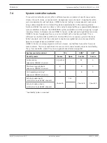
Page 61: ...declarations Europe CE CPR Environment RoHS 7 8 Technical data Electrical Control Audio routing SCL SCM SCS OMNEO channels Unlimited 32 4 Tone message playback SCL SCM SCS OMNEO channels 8 8 4 External audio inputs and or outputs SCL SCM SCS Dante or AES67 channels 120 8 4 Logging internal storage Call events Fault events General events 1000 1000 1000 Real Time Clock Accuracy with NTP Accuracy no ...

Page 62: ...lt watchdog reset All processors System integrity Fault report time 100 s Site specific data integrity Fault report time Supervised message storage 1 hour 90 min Power supply input A B Undervoltage Network interface Ethernet Protocol Redundancy 100BASE TX 1000BASE T TCP IP RSTP Audio control protocol Network audio latency Audio data encryption Control data security OMNEO 10 ms AES128 TLS Ports 5 E...

Page 63: ...ating 500 to 5000 m 1640 to 16404 ft Vibration operating Amplitude Acceleration 0 7 mm 2 G Bump transport 10 G Mechanical Enclosure Dimensions WxHxD With mounting brackets Rack unit 483 x 44 x 400 mm 19 x 1 75 x 15 7 in 19 in 1U Ingress protection IP30 Case Material Color Steel RAL9017 Frame Material Color Zamak RAL9022HR Weight 5 8 kg 12 8 lb ...

Page 64: ...ker output power of 600 W Flexible partitioning of the available output power across all amplifier channels to use it effectively significantly reducing the amount of required amplifier power in a system Cost and space saving integrated independent spare channel for fail safe redundancy High efficiency in all operating conditions dissipation and heat loss is minimized to save on energy and battery...

Page 65: ...ing Tree Protocol RSTP for loop through connections to adjacent devices Dual 48 VDC inputs with polarity reversal protection each with a full power DC DC converter operating in tandem for redundancy Fully independent amplifier channels the integrated spare channel automatically replaces a failing channel with due regard of the actual sound processing settings All amplifier channels support two ind...

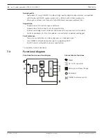
Page 66: ... 3 Functional diagram Functional and connection diagram Internal device functions 1 A 1 B 1 2 3 4 2 A 2 B 3 A 3 B 4 A 4 B 1 2 3 4 A B 2 1 DC to DC converter Audio processing DSP OMNEO network switch Controller Lifeline control interface Lifeline supply input Lifeline audio input 1 4 Amplifier channel Spare channel ...

Page 67: ...feline substitute White Network link to system controller present Network link lost Green Yellow Power on Green Identification mode Indicator test All LEDs blink Rear panel indicators and controls 100 Mbps network 1 Gbps network Yellow Green Device fault present Yellow Power on Green Device reset to factory default Button Identification mode Indicator test All LEDs blink Rear panel connections Saf...

Page 68: ... Parts included The box contains the following parts Quantity Component 1 Amplifier 600W 4 channel 1 Set of 19 rack mounting brackets pre mounted 1 Set of screw connectors and cables 1 Quick Installation Guide 1 Important Product Information No tools or Ethernet cables are provided with the device Parts check and identification x8 x2 x1 x2 x1 B x4 D C H x12 E F G A Amplifier B 2 pole screw plug x2...

Page 69: ...way any dangerous currents that might occur due to malfunction or accident Use a thick multi strand wire 2 5 mm2 with wire eyelets and washers for a solid connection The safety ground connection is needed as reference for the ground short detection circuit Without this connection the amplifier could be electrically floating and no ground shorts or leakage currents would be detected for loudspeaker...

Page 70: ...B observing polarity Wiring color convention red for and black for Use a flat blade screwdriver to tighten each connection 3 Insert the cable into the 48 V input A cut the cable to length and mount the connector of the powering device to the other end of the cable again observing polarity Insert this connector into output A of the powering device 4 For redundancy repeat these steps for a second ca...

Page 71: ...ds information pin 1 to the connected amplifier about the availability of mains power In case mains power fails and power is provided from the battery this signal sets the amplifier in backup power mode to disable all amplifier channels that are not needed to make calls with a priority above the configured priority level for the backup power mode When no high priority calls are being made via this...

Page 72: ...he other end of the cable observing wiring order Insert this connector into the lifeline socket of the multifunction power supply Notice The lifeline connection may not be longer than 3 m 8 5 5 Amplifier outputs The amplifier provides four output channels and a spare channel that substitutes a failing channel The channels have direct drive 70 100 V outputs for low distortion low crosstalk and a wi...

Page 73: ...insulated terminals or wiring may result in an unpleasant sensation Notice Only amplifier channel 1 and the spare channel are capable of delivering up to 600 W maximum All other channels are limited to 300 W maximum In practice this does not impose any limitation on the flexibility of partitioning the total amplifier power across the channels because if there is one zone with more than 300 W load ...

Page 74: ...issible attenuation of the acoustic sound level due to loudspeaker line losses See also section Cable type recommendations page 23 for loudspeaker cable size recommendations 2 Insert the near end wires of the loudspeaker cable into slots 1 and 2 of connector D preferably using crimped on wire ferrules that fit to the wire gauge used Observe polarity Use a flat blade screwdriver to tighten each con...

Page 75: ... level will drop by 3 dBSPL A loudspeaker line fault will be reported 1 Connect half of the loudspeakers in parallel in a loop through fashion to output A Observe polarity Follow the same wiring procedure as for using a single line 2 Connect an end of line device to the end of loudspeaker line A 3 Repeat this procedure for the other half of the loudspeakers and connect them to output B 4 Connect a...

Page 76: ...activated to drive the loop from the opposite side in an attempt to reach all loudspeakers again A loudspeaker line fault will be reported Follow the procedure below to connect the loudspeakers according to this scheme 1 Connect all loudspeaker in parallel in a loop through fashion Observe equal polarity for all loudspeakers Connect one side of the loudspeaker cable to output A observing polarity ...

Page 77: ...r PRAESENSA device in the same rack 4 The second port of the amplifier can be connected to a subsequent PRAESENSA device The built in Ethernet switch allows for a loopthrough interconnection between system devices with a maximum of 21 devices in series 5 For redundancy a looped through network connection may be connected at both sides to create a loop RSTP must be enabled in the system 6 For confi...

Page 78: ...ope CE CPR Environment RoHS 8 7 Technical data Electrical Loudspeaker load Maximum loudspeaker load 100 V mode all channels 70 V mode all channels 600 W 600 W Minimum loudspeaker load impedance 100 V mode all channels 70 V mode all channels 16 7 ohm 8 3 ohm Maximum cable capacitance 100 V mode all channels 70 V mode all channels 2 uF 2 uF All channels combined Amplifier outputs Maximum voltage swi...

Page 79: ...1 1 0 1 Signal to Noise Ratio SNR 100 V mode 20 Hz to 20 kHz 70 V mode 20 Hz to 20 kHz 110 dBA 107 dBA Crosstalk between channels 100 Hz to 20 kHz 84 dBA DC offset voltage 50 mV Signal processing per channel Audio equalization Level control Level control resolution Audio delay Audio delay resolution RMS power limiter 7 section parametric 0 to 60 dB mute 1 dB 0 to 60 s 1 ms Rated power Life line Se...

Page 80: ...und short detection loudspeaker lines 50 kohm Amplifier channel redundancy switching Internal spare channel Amplifier channel load Short circuit Loudspeaker line redundancy switching A B group Class A loop Controller continuity Watchdog Temperature Overheat Fan Rotation speed Network interface Link presence Network interface Ethernet Protocol Redundancy 100BASE TX 1000BASE T TCP IP RSTP Audio cont...

Page 81: ...ation operating Amplitude Acceleration 0 7 mm 2 G Bump transport 10 G Airflow Fan airflow Front to sides rear Fan noise Idle condition 1 m distance Rated power 1 m distance 30 dBSPLA 53 dBSPLA Mechanical Enclosure Dimensions WxHxD With mounting brackets Rack unit 483 x 44 x 400 mm 19 x 1 75 x 15 7 in 19 in 1U Ingress protection IP30 Case Material Color Steel RAL9017 Frame Material Color Zamak RAL9...

Page 82: ...edundancy High efficiency in all operating conditions dissipation and heat loss is minimized to save on energy and battery capacity for backup power Flexible partitioning of the available output power across all amplifier channels to use it effectively significantly reducing the amount of required amplifier power in a system Flexibility in loudspeaker topologies A B outputs on every amplifier chan...

Page 83: ... of the actual sound processing settings All amplifier channels support two independent loudspeaker groups A and B enabling redundant loudspeaker wiring topologies Backup analog audio lifeline input driving the spare amplifier channel to serve all connected loudspeaker zones in case both network connections or the amplifier network interface would fail 9 3 Functional diagram Functional and connect...

Page 84: ...w Audio lifeline substitute White Network link to system controller present Network link lost Green Yellow Power on Green Identification mode Indicator test All LEDs blink Rear panel indicators and controls 100 Mbps network 1 Gbps network Yellow Green Device fault present Yellow Power on Green Device reset to factory default Button Identification mode Indicator test All LEDs blink Rear panel conne...

Page 85: ...tion page 13 9 5 1 Parts included The box contains the following parts Quantity Component 1 Amplifier 600W 8 channel 1 Set of 19 rack mounting brackets pre mounted 1 Set of screw connectors and cables 1 Quick Installation Guide 1 Important Product Information No tools or Ethernet cables are provided with the device Parts check and identification A Amplifier B 2 pole screw plug x2 C 6 pole screw pl...

Page 86: ...he ground short detection circuit Without this connection the amplifier could be electrically floating and no ground shorts or leakage currents would be detected for loudspeaker lines that touch ground somewhere The safety ground connection via the mains connection of the multifunction power supply cannot be relied on for this because the mains cable of this supply could be unplugged and then the ...

Page 87: ...vice 4 For redundancy repeat these steps for a second cable between output B of the powering device to input B of the amplifier 5 Alternatives Instead of using the A B outputs of a PRAESENSA powering device also two separate power supplies can be used The maximum current rating of the supply connectors is 15 A only use a 48 V power supply that is current limited to 15 A also in overload condition ...

Page 88: ... channels that are not needed to make calls with a priority above the configured priority level for the backup power mode When no high priority calls are being made via this amplifier it informs the multifunction power supply pin 2 to switch off the 48 V converters to minimize battery power consumption even more The power supplies and the amplifier channels go to snooze mode and wake up every 90 s...

Page 89: ...r the output power of each channel Every channel also has a load independent flat frequency response This combination of features makes it possible to partition the available amplifier power across all channels and utilize that power effectively Every channel has a 4 pole connector socket providing independently switched loudspeaker group A and group B outputs It supports three different loudspeak...

Page 90: ...le attenuation of the acoustic sound level due to loudspeaker line losses See also section Cable type recommendations page 23 for loudspeaker cable size recommendations 2 Insert the near end wires of the loudspeaker cable into slots 1 and 2 of connector D preferably using crimped on wire ferrules that fit to the wire gauge used Observe polarity Use a flat blade screwdriver to tighten each connecti...

Page 91: ...l will drop by 3 dBSPL A loudspeaker line fault will be reported 1 Connect half of the loudspeakers in parallel in a loop through fashion to output A Observe polarity Follow the same wiring procedure as for using a single line 2 Connect an end of line device to the end of loudspeaker line A 3 Repeat this procedure for the other half of the loudspeakers and connect them to output B 4 Connect an end...

Page 92: ...one side of the loudspeaker cable to output A observing polarity 2 Connect the other side of the loudspeaker cable to output B In this case maintaining the correct polarity is especially important as reversal on one end will short circuit the amplifier channel not immediately but when output B is activated in case of interruption of one conductor 3 Connect an end of line device to output B in para...

Page 93: ...PRAESENSA device in the same rack 4 The second port of the amplifier can be connected to a subsequent PRAESENSA device The built in Ethernet switch allows for a loopthrough interconnection between system devices with a maximum of 21 devices in series 5 For redundancy a looped through network connection may be connected at both sides to create a loop RSTP must be enabled in the system 6 For configu...

Page 94: ...ope CE CPR Environment RoHS 9 7 Technical data Electrical Loudspeaker load Maximum loudspeaker load 100 V mode all channels 70 V mode all channels 600 W 600 W Minimum loudspeaker load impedance 100 V mode all channels 70 V mode all channels 16 7 ohm 8 3 ohm Maximum cable capacitance 100 V mode all channels 70 V mode all channels 2 uF 2 uF All channels combined Amplifier outputs Maximum voltage swi...

Page 95: ...1 1 0 1 Signal to Noise Ratio SNR 100 V mode 20 Hz to 20 kHz 70 V mode 20 Hz to 20 kHz 110 dBA 107 dBA Crosstalk between channels 100 Hz to 20 kHz 84 dBA DC offset voltage 50 mV Signal processing per channel Audio equalization Level control Level control resolution Audio delay Audio delay resolution RMS power limiter 7 section parametric 0 to 60 dB mute 1 dB 0 to 60 s 1 ms Rated power Life line Se...

Page 96: ...und short detection loudspeaker lines 50 kohm Amplifier channel redundancy switching Internal spare channel Amplifier channel load Short circuit Loudspeaker line redundancy switching A B group Class A loop Controller continuity Watchdog Temperature Overheat Fan Rotation speed Network interface Link presence Network interface Ethernet Protocol Redundancy 100BASE TX 1000BASE T TCP IP RSTP Audio cont...

Page 97: ...ation operating Amplitude Acceleration 0 7 mm 2 G Bump transport 10 G Airflow Fan airflow Front to sides rear Fan noise Idle condition 1 m distance Rated power 1 m distance 30 dBSPLA 53 dBSPLA Mechanical Enclosure Dimensions WxHxD With mounting brackets Rack unit 483 x 44 x 400 mm 19 x 1 75 x 15 7 in 19 in 1U Ingress protection IP30 Case Material Color Steel RAL9017 Frame Material Color Zamak RAL9...

Page 98: ...ot tone detection from the amplifier with feedback to the amplifier using the loudspeaker line itself No additional wiring is needed for fault or status reporting The A B outputs of a PRAESENSA amplifier channel are supervised individually with separate end of line devices To reduce power consumption PRAESENSA amplifier channels use pilot tone modulation The audibility of the pilot tone is virtual...

Page 99: ...nections Device connections Loudspeaker line 10 5 Installation 10 5 1 Parts included The box contains the following parts Quantity Component 8 End of line device 8 Set of connection wires with thermal fuse 1 Quick Installation Guide 1 Important Product Information The PRA EOL can only be ordered in multiples of eight devices packed in one box No tools are provided with the device Parts check and i...

Page 100: ...ith the thermal fuse at the loudspeaker side This is the primary side of the loudspeaker transformer The polarity is not important for the end of line device but it is good practice to connect the wire with the thermal fuse to the positive loudspeaker terminal The thermal fuse is to disconnect the end of line device and its wires from the loudspeaker line in case of fire This prevents that the lou...

Page 101: ...and snapped in place as bottom plate 2 3 Then the device can be mounted outside the loudspeaker cabinet or inside a cable junction box Notice When selecting cables and wire gauge for loudspeaker connections take into account the length and loudspeaker load to avoid excessive power loss Make sure that the signal level at the end of the loudspeaker line has not dropped with more than 2 dB this is ap...

Page 102: ...missions EN 55032 EN 61000 6 3 ICES 003 ANSI C63 4 FCC 47 part 15B class A Plenum rating UL 2043 Conformity declarations Europe CE CPR Environment RoHS 10 7 Technical data Electrical Control Pilot tone detection Frequency Level 25 5 kHz 1 5 3 VRMS Amplifier load 100 mW Loudspeaker cable Maximum length Maximum capacitance Operating temperature 1000 m 80 nF 20 to 50 C 4 to 122 F Maximum input voltag...

Page 103: ...22 to 158 F Humidity non condensing 5 to 95 Air pressure operating 560 to 1070 hPa Altitude operating 500 to 5000 m 1640 to 16404 ft Vibration operating Amplitude Acceleration 0 7 mm 2 G Bump transport 10 G Mechanical Enclosure Dimensions WxHxD Board shape Box shape 78 x 60 x 16 mm 3 1 x 2 4 x 0 6 in 45 x 60 x 18 mm 1 8 x 2 4 x 0 7 in Ingress protection IP30 Case Material Color Plastic RAL3000 Wei...

Page 104: ...upplies Three fully independent 48 VDC power supplies for up to three amplifiers One 24 VDC output for a system controller or auxiliary device All power supply outputs have double connectors for A B dual redundant wiring to the connected loads A fault condition on one of the outputs does not affect any of the other outputs Universal mains input with power factor correction to maximize the amount o...

Page 105: ...s General purpose control inputs and outputs Eight control inputs to receive signals from external systems with configurable connection supervision Eight voltage free single pole double throw SPDT relay contacts to activate external devices Control input and output functions are software configurable Fault tolerance and supervision Supervision of mains battery and device operation and all connecti...

Page 106: ... device functions 1 2 3 4 5 6 7 8 1 2 3 4 5 6 7 8 1 A B 2 A B 3 A B A B 2 1 4 3 6 5 PoE SFP Power over Ethernet power source OMNEO network switch SFP Socket for SFP module Controller Audio processing DSP Mains to DC converter DC to DC converter Battery charger Control input processor Control output relay Lifeline audio output Lifeline supply output Lifeline control interface Diode Fuse ...

Page 107: ...work link to system controller present Network link lost Green Yellow Battery status Full float charging Charging bulk or absorption charging Fault Green Green blinking Yellow Mains present Mains fault Green Yellow Identification mode Indicator test All LEDs blink Rear panel indicators and controls 100 Mbps network 1 Gbps network Yellow Green Device fault present Yellow Power on Green Device reset...

Page 108: ...6 11 5 Installation The device is designed to be installed in a 19 rack cabinet Refer to Mounting the 19 rack devices page 20 The device can be connected everywhere within the PRAESENSA system If required refer to System introduction page 13 11 5 1 Parts included The box contains the following parts Quantity Component 1 Multifunction power supply 1 Set of 19 rack mounting brackets pre mounted 1 Se...

Page 109: ...It is recommended to mount the fuse at the battery side see chapter below immediately at the positive battery terminal Alternatively the fuse can be mounted at the power supply side see chapter below when local standards require so Never use two fuses one on each side because this would increase the series resistance of the cable assembly and the high peak currents of a system in emergency mode wo...

Page 110: ...losion if an incorrect type of battery is used Notice 1 To prevent damage to the battery always check the depth of the threaded insert of the terminals before tightening the bolts If needed use shorter bolts 2 Make sure that all connections are tightened with the correct torque Not only to prevent damage but also to keep the contact resistances as low as possible It is good practice to keep the re...

Page 111: ... single 12 V battery that has all six battery cells at the same temperature and all cells using the same electrolyte All cell voltages will be substantially equal and the switch over to the next charging state is well defined Series connected batteries without battery balancing circuits will not stabilize to the exactly same voltage while the switch over to the next charging state is determined by...

Page 112: ...terminal using the other M8 self locking nut K Tighten with torque 5 Nm 3 Insert the connector of the battery temperature sensor assembly J into the temperature sensor connector socket of the power supply 4 Connect the open end of the black cable O to the negative battery terminal with the eyelet of the temperature sensor J on top Depending on the type of battery and its terminals use a short M8 b...

Page 113: ...cking nut K Tighten with torque 5 Nm When the black O and red N battery cables are fixed to each other make sure that the isolated fuse eyelet on the red cable N is at the power supply side otherwise reverse the complete cable set 2 Put the fuse M on the long positive battery connection terminal of the power supply followed by the isolated eyelet of the red cable N with the metal side of the eyele...

Page 114: ...is about the same as for the 100 A CF8 fuse M less than 1 mohm so the impedance measurement of the battery circuit which is a requirement of the voice alarm standards is not affected Do not use multiple fuses or circuit breakers in series or double pole circuit breakers as this will increase the impedance of the battery circuit and may generate a premature battery fault Battery cables Battery cabl...

Page 115: ...3 6 0 58 170 35 0 55 180 1 42 4 0 46 210 50 0 39 250 11 5 3 Mains power connection 1 Check that the mains AC power supply meets the nominal input rating of the PRA MPS3 The voltage that can be applied is any of the nominal power supply voltages in the range of 115 VAC to 240 VAC The frequency is 50 Hz or 60 Hz 2 Use the supplied power cord I to connect to the mains line If the supplied power cord ...

Page 116: ... and cable redundancy This is especially useful when the amplifiers and the power supply are not in the same rack and the power supply cable is accessible or vulnerable It is recommended to always use both connections B PRA AD60x 1 2 3 Connection procedure 1 The power supply interconnection wiring and ferrules are delivered with the amplifier The power supply terminal plugs B are delivered with th...

Page 117: ...ervised by the multifunction power supply The multifunction power supply sends information pin 1 to the connected amplifier about the availability of mains power In case mains power fails and power is provided from the battery this signal sets the amplifier in backup power mode to disable all amplifier channels that are not needed to make calls with a priority above the configured priority level f...

Page 118: ...le connector C for the multifunction power supply is delivered with the power supply 3 Mount the connector C to the cable following the same wire order as for the amplifier side the cable should be reversible 4 Insert the connector C into the lifeline socket of the multifunction power supply using the socket next to the 48 V outputs that go to the same amplifier Notice Each pair of 48 V outputs A ...

Page 119: ...power supply cable is accessible or vulnerable It is recommended to always use both connections D PRA SCx Connection procedure 1 The power supply interconnection wiring and ferrules are delivered with the system controller The power supply terminal plugs D are delivered with the multifunction power supply 2 Follow the power supply cable assembly instructions as provided for the system controller O...

Page 120: ...ation with four extensions which is the maximum A PRAESENSA call station has two Ethernet ports and can be connected with two cables for fail safe cable redundancy It is also possible to connect a call station to two separate multifunction power supplies for additional protection against failure of its Ethernet switch Ports 3 to 5 cannot be used for PoE powering PRA CSLx PoE devices can simply be ...

Page 121: ... hostname is the type number of the device without the dash followed by a dash and then the last 6 hexadecimal digits of its MAC address Configuration is described in the PRAESENSA configuration manual PRA 1 Connect at least one of the ports to the network so that it can be discovered by the system controller to make it part of the system 2 The other ports can be used for a loop through connection...

Page 122: ...nections are needed e g to make the devices in the cluster part of a long distance fiber ring at least two fiber ports are needed from two multifunction power supplies or from a stand alone network switch with two SFP sockets or a combination of these PRA SFPSX 550 m PRA SFPLX 10 km 1 2 PRA SFPxX Caution Risk of eye injury When inspecting a connector ensure that light sources are off The light sou...

Page 123: ...onnected in such a way that the control input sees 20 kohm for an open contact and 10 kohm for a closed contact In case of a cable interruption the control input sees a very high resistance In case of a cable short circuit the control input sees a very low resistance A very high or very low resistance will be interpreted as a fault condition E 10 k 10 k 12 1 8 34 Connection procedure with and with...

Page 124: ...t The control outputs can be configured independently for various actions Make sure not to exceed the maximum contact rating Refer to the Control output contact rating graphic below F 1 4 5 8 2 3 456 Connection procedure 1 Use a 2 wire or 3 wire cable proper for the installation and application and one of the 12 pole terminal plugs delivered with the device 2 Insert the near end wires of the cable...

Page 125: ...ured device is removed from a system to become part of another system See Device status and reset page 51 11 6 Approvals Emergency standard certifications Europe EN 54 16 EN 54 4 International ISO 7240 16 ISO 7240 4 Regulatory areas Safety EN IEC CSA UL 62368 1 Immunity EN 55024 EN 55103 2 E1 E2 E3 EN 50130 4 Emissions EN 55032 EN 61000 3 2 EN 61000 3 3 EN 61000 6 3 ICES 003 ANSI C63 4 FCC 47 part...

Page 126: ...V 90 A 9 V Battery charger Nominal charging current Nominal float voltage Float voltage control Temperature sensor NTC Charging temperature range 8 5 A 13 5 V 21 9 mV C 10 kohm β 3984 K 15 to 50 C 48 VDC outputs 1 3 Nominal DC output voltage Maximum continuous current Maximum peak current 48 V 5 5 A 7 0 A 24 VDC output Nominal DC output voltage Maximum continuous current Maximum peak current 24 V ...

Page 127: ...E output 1 2 Lifeline DC outputs 1 3 5 5 A 5 5 A 0 A 0 7 A 0 7 A 0 A 0 3 A 0 3 A 0 A 0 7 A 0 7 A 0 A Output voltage range 48 VDC outputs 1 3 24 VDC output PoE output 1 2 Lifeline DC outputs 1 3 46 to 50 V 23 to 25 V 44 to 57 V 9 to 18 V Maximum impedance of battery circuit 230 Ah battery 180 Ah battery 140 Ah battery 100 Ah battery 7 1 mohm 8 6 mohm 9 8 mohm 11 0 mohm Control interface Control inp...

Page 128: ...tion Impedance Control input connections Open short Temperature Per section Fan Rotation speed Controller continuity Watchdog Network interface Link presence Network interface Ethernet Protocol Redundancy 100BASE TX 1000BASE T TCP IP RSTP Audio control protocol Network audio latency Audio data encryption Control data security OMNEO 10 ms AES128 TLS Ports RJ45 SFP 5 2 with PoE 1 Environmental Clima...

Page 129: ... Amplitude Acceleration 0 7 mm 2 G Bump transport 10 G Airflow Fan airflow Front to sides rear Fan noise Idle condition 1 m distance Rated power 1 m distance 30 dBSPLA 53 dBSPLA Mechanical Enclosure Dimensions WxHxD With mounting brackets Rack unit 483 x 88 x 400 mm 19 x 3 5 x 15 7 in 19 in 2U Ingress protection IP30 Case Material Color Steel RAL9017 Frame Material Color Zamak RAL9022HR Weight 11 ...

Page 130: ... also as emergency call station The stylish design incorporates a supervised microphone an internal monitor loudspeaker and a socket to insert a local audio source for background music The 4 3 high resolution full color capacitive touch screen gives the operator optimum control and feedback at all times Every call station must have at least one PRA CSE call station extension for zone selection wit...

Page 131: ...f the call station is not used for a while it will switch to sleep mode to save energy It will immediately wake up when the screen or a button is touched Only valid for the PRA CSLD Press to talk button gives tactile feedback and is recessed to prevent accidental use Only valid for the PRA CSLW Press to talk switch on hand held microphone Emergency operation The call station fully complies to the ...

Page 132: ...status LED ring PRA CSLW 12 4 Indicators and connections PRA CSLD PRA CSLW Top side indicators Power on Device in identification mode Green Green blinking System fault present Yellow PRA CSLD Status business call Microphone active Chime message active Status emergency call Microphone active Alarm tone message active Green Green blinking Red Red blinking 4 3 full color capacitive touch screen LCD ...

Page 133: ...Green blinking Red Red blinking Identification mode Indicator test All LED s blink Top side controls Press To Talk Button 4 3 full color capacitive touch screen LCD Fixed hand held Press To Talk Microphone Switch Bottom side indicators and controls 100 Mbps network 1 2 1 Gbps network1 2 Yellow Green Device reset to factory default Button Bottom side and side interconnections Network port 1 2 PoE P...

Page 134: ...eatsink 12 5 1 Parts included The box contains the following parts PRA CSLD Quantity Component 1 Desktop LCD call station 1 Bracket attached to bottom 1 Connector cover attached to bottom 1 Quick Installation Guide 1 Important Product Information PRA CSLW Quantity Component 1 Wallmount LCD call station 1 Bracket attached to bottom 1 Connector cover attached to bottom 1 Microphone clip 1 Quick Inst...

Page 135: ...rts take PoE power for cable redundancy and supply redundancy For best availability it is advised to connect each port to a different independent PSE such as a PRA MPS3 multifunction power supply ports 1 and 2 or a PRA ES8P2S Ethernet switch ports 1 8 In case one of the connections fail or one of the PSE sources fail the operation of the call station is not affected With both connections to the sa...

Page 136: ...ontroller Configuration of the call station and its extensions is done via the system controller For configuration the call station is identified by its hostname which is printed on the product label on the bottom of the device The format of the hostname is the type number of the device without the dash followed by a dash and then the last 6 hexadecimal digits of its MAC address Configuration is d...

Page 137: ...one or more system zones This input is not supervised unplugging the cable to the audio player will not be reported as a fault Notice When music is played from a PC that is connected to a grounded mains supply there is a risk of hum being inserted into the music input of the call station This is caused by unequal ground potentials of the different mains supplies Use a cable with integrated transfo...

Page 138: ...y of the voice sound In environments that are not extremely noisy the sound can be improved by applying parametric equalization on this call station lifting the frequency band between 300 Hz and 1 kHz as shown in the next diagram This makes the frequency response more flat between 300 Hz and 6 kHz A low cut filter below 300 Hz helps to improve speech intelligibility See the PRAESENSA configuration...

Page 139: ...r vertical mounting below 2m height 12 5 8 Reset to factory default The reset switch resets the device to its factory default settings This function is only to be used in case a secured device is removed from a system to become part of another system See Device status and reset page 51 12 6 Approvals Emergency standard certifications Europe EN 54 16 International ISO 7240 16 Regulatory areas Safet...

Page 140: ...W Nominal acoustic input level configurable 85 to 105 dBSPL Maximum acoustic input level 120 dBSPL Signal to Noise Ratio SNR 73 dBA Directivity Unidirectional Frequency response 3 6 dB 500 Hz to 8 kHz noise cancelling Display Size 4 3 Touch screen Capacitive Color depth 24 bit Resolution 480 x 272 px Brightness 300 cd m2 Monitor loudspeaker Nominal acoustic input level Between 500 Hz and 3 kHz at ...

Page 141: ...one Audio path Controller continuity PoE 1 2 Current Pilot tone Watchdog Voltage Supervision PRA CSLW Supervision Microphone Audio path Press to talk switch Controller continuity PoE 1 2 Impedance Pilot tone Impedance Watchdog Voltage Network interface Ethernet Protocol Redundancy 100BASE TX 1000BASE T TCP IP RSTP Audio control protocol Network audio latency Audio data encryption Control data secu...

Page 142: ...tion IP30 Mechanical Enclosure PRA CSLD Dimensions WxHxD Excluding microphone 130 x 62 x 189 mm 5 12 x 2 44 x 7 44 in Base Material Color Zamak RAL9017 Panel Material Color Plastic RAL9017 RAL9022HR Weight 0 9 kg 1 98 lb Enclosure PRA CSLW Dimensions WxHxD 130 x 62 x 189 mm 5 12 x 2 44 x 7 44 in Base Material Color Zamak RAL9017 Panel Material Color Plastic RAL9017 RAL9022HR Weight 1 0 kg 2 21 lb ...

Page 143: ... section on top 13 2 Functions Business operation Connection of up to four PRA CSE extensions each with twelve buttons The buttons can be configured for various functions but they are especially useful for zone selection giving a clear overview of accessible zones and the LED indicators for each button show the status of the respective zone like being selected occupied or at fault Emergency operat...

Page 144: ...al and connection diagram Internal device functions 1 12 Controller Zone status indicator Zone fault indicator 13 4 Indicators and connections Top side indicators Selection button LED ring 1 12 Selected White Active 1 12 Evacuation call Business call Music Red Blue Green Zone fault present 1 12 Yellow Top side controls Selection 1 12 Button ...

Page 145: ...PRA CSE is used in combination with a PRA CSLD and PRA CSLW call station Refer to LCD call station PRA CSLD PRA CSLW page 130 13 5 1 Parts included The box contains the following parts Quantity Component 1 Call station extension 1 Bracket attached to bottom 1 Metal coupling plate 4 screws 1 RJ12 interconnection cable 1 Button cap x3 1 Quick Installation Guide 1 Important Product Information No too...

Page 146: ...ers at the bottom of the call station and the extension using a TX10 screwdriver For the call station get access to the two screws via the holes in the table stand bracket 2 Mount the coupling plate between the call station and the first extension using four M3 screws with TX10 head Mounting plate and screws are included with the extension An extension can only be mounted to a call station on its ...

Page 147: ...ift up the top cover 2 Slide the cover upwards to remove it 3 Turn the cover upside down Gently push a screwdriver of tweezers into the hole in the metal top side label holder Slide the label holder to the left to unlock and then up to remove This label holder is for the title label of the extension It is made of metal and is also used to fix the top cover magnetically to the body of the enclosure...

Page 148: ...tems B V 6 Place the labels upside down in the label slots and put the label holders back in place Slide the metal top side label holder to the right to lock it in place 7 Mount the cover back on the extension body by first sliding the bottom side into the body then tilt down until it snaps into place ...

Page 149: ...p the top cover 2 Slide the cover upwards to remove it and get access to the buttons 3 Translucent light rings are placed in rows of three around the buttons Use tweezers to lift and remove the row for the button that should get a cap 4 Remove the original light ring by cutting the plastic bridges to the adjacent light rings Leave part of the plastic bridges in place around each light ring for bet...

Page 150: ...nge for the right pivot pin Rotate the cap 10 degrees counterclockwise and slide to the right over the button so the left pivot pin goes into the hole of the hinge Then push the right side of the cap down until the right pivot pin snaps into the slot of the hinge This requires some force 9 After the cap has snapped into place the hinge has two stable positions and the cap can be flipped into the o...

Page 151: ...C 47 part 15B class A Conformity declarations Europe CE CPR Environment RoHS 13 7 Technical data Electrical Power transfer Power supply input Input voltage Input voltage tolerance Power consumption indicators off on 5 VDC 4 5 to 5 5 VDC 0 1 W 1 0 W Supervision Interconnection Link presence Processor Watchdog Environmental Climatic conditions Temperature Operating Storage and transport 5 to 50 C 23...

Page 152: ...allation manual Bosch Security Systems B V Climatic conditions Ingress protection IP30 Mechanical Enclosure Dimensions WxHxD 130 x 62 x 189 mm 5 12 x 2 44 x 7 44 in Base Material Color Zamak RAL9017 Panel Material Color Plastic RAL9017 RAL9022HR Weight 0 4 kg 0 88 lb ...

Page 153: ... interconnections on glass fiber or more PoE enabled ports are needed to power PRAESENSA call stations 14 2 Functions Intended for PA VA systems Managed industrial Gigabit Ethernet switch with convection cooling and DIN rail mounting designed for long term continuous operation Redundant wide range DC power input Protected against overloads and short circuits Comes with pre installed and pre config...

Page 154: ... broadcasting Support for Simple Network Management Protocol SNMP and Link Layer Discovery Protocol LLDP All copper ports provide PoE IEEE 802 3 af at to power PRAESENSA call stations or other devices Fault tolerance All ports support RSTP for loop connections to adjacent devices with recovery from a broken link Dual redundant 24 to 48 V DC inputs 14 3 Functional diagram Functional and connection ...

Page 155: ...n Port 1 10 100 Mbps network 1 Gbps network Yellow Green R M Active when determining ring master Green PWR1 Power on power supply input 1 Green PoE 1 8 PoE activated Green PWR2 Power on power supply input 2 Green Reset System soft reset or factory reset Switch Alarm SFP port disconnected or link down Red Front panel connections Port 1 8 Network port 1 8 with PoE Port 9 10 Network combo port 9 10 C...

Page 156: ...il or on a wall or panel using the wall mounting brackets Notice For security reasons change the factory default password of the switch Notice PRAESENSA supervises the network links between OMNEO devices but a link between two non OMNEO devices is not supervised The PRA ES8P2S is not a native OMNEO device and a connection between two of these switches is not supervised 14 5 1 Parts included The bo...

Page 157: ...remaining power capacity of the 48 V supply is not sufficient anymore for an amplifier under various load conditions The lifeline that belongs to the powering 48 V output is not used so the 48 V output will not be disabled as would be for amplifiers in sleep snooze mode to save power It is also essential that the 48 V for the switch is not disabled at any time In case of mains failure the switch w...

Page 158: ... VDC 16 8 to 62 4 VDC Power consumption 48 V Active mode no PoE Active mode with PoE 12 W 140 W Power over Ethernet Standard Output power all ports together Output power per port 1 8 IEEE 802 3 af at 120 W 30 W Supervision Redundant power failure P Fail relay Alarm LED Port link down P Fail relay Alarm LED Fiber link down P Fail relay Alarm LED Device status reporting SNMP SMTP Network interface E...

Page 159: ...LAN Group Arrange IEEE 802 1Q 256 VLAN ID1 4094 Port based Q in Q GVRP Multicast IGMP snooping v1 v2 v3 MLD snooping IGMP immediate leave Energy Efficient Ethernet IEEE 802 3az EEE Redundancy IEEE 802 1D STP IEEE 802 1s MSTP IEEE 802 1w RSTP QoS Priority queue scheduling SP WRR Class of service CoS IEEE 802 1p DiffServ DSCP Rate limiting Ingress Egress Link aggregation IEEE 802 3ad Static Dynamic ...

Page 160: ...agement DHCP Client Server Access SNMP v1 v2c v3 RMON Telnet SSH HTTP S CLI Software upgrade TFTP HTTP dual image NTP SNTP client Mechanical Enclosure Dimensions WxHxD 74 x 152 x 105 mm 2 9 x 6 0 x 4 1 in Ingress protection IP30 Mounting TS35 DIN Rail EN 60715 Wall mounting Case Aluminum Weight 1 3 kg 2 7 lb ...

Page 161: ...or maximum performance reliability and flexibility Both transceivers are certified for EN 54 16 in combination with PRAESENSA systems 15 2 Functions Features a duplex LC connector one connection for transmit and the other for receive Fits and locks into the SFP socket of the PRA MPSx and PRA ES8P2S SFP is the popular industry format jointly developed and supported by many network component vendors...

Page 162: ...e following parts Quantity Component 1 SFP fiber transceiver No tools or Ethernet cables are provided with the device 15 4 2 Application Fiber transceivers are especially beneficial in environments where high levels of electromagnetic interference EMI is a common phenomenon like industrial plants This interference can cause data corruption over copper based Ethernet links However data transmitted ...

Page 163: ...ly the vendor s own modules As a result this means that the PRA SFPLX and PRA SFPSX may not work in some brands of Ethernet switches 15 4 3 Transceiver To install an SFP transceiver follow the procedure below 1 An SFP transceiver can be damaged by static electricity Be sure to observe all standard electrostatic discharge ESD precautions such as wearing an antistatic wrist strap to avoid damaging t...

Page 164: ...7240 16 Regulatory areas Safety Laser Class I IEC 60825 1 Conformity declarations Europe CE CPR USA Canada FCC c UL Environment RoHS 15 6 Technical data PRA SFPSX Electrical Interface Supply voltage 3 3 V Power consumption 0 5 W Speed IEEE 802 3z 1000BASE SX Transmitter power 4 to 9 5 dBm Receiver sensitivity 18 dBm Connection Hot swappable Locking Optical Interface Connector type Dual LC Wave len...

Page 165: ...tivity 20 dBm Connection Hot swappable Locking Optical Interface Connector type Dual LC Wave length 1310 nm Fiber length 10 km 32 821 ft Optical fiber Single mode Core size ITU T G 652 SMF PRA SFPSX and PRA SFPLX Environmental Climatic conditions Temperature Operating Storage and transport 40 to 85 C 40 to 185 F 40 to 85 C 40 to 185 F Humidity non condensing 5 to 95 Mechanical Enclosure Dimensions...

Page 166: ...bution network The mains is supplied via a 3 pole screw plug that requires the module to be installed by professional installers and mounted in a safe place without user access PRA PSM24 Compact DIN rail mounted power supply delivering 24 V at up to 10 A continuously for powering various utilities and devices in Public Address systems Adjustable output voltage 24 to 28 V For fail safe redundancy i...

Page 167: ...utomatic recovery Over temperature protection with automatic recovery 16 3 Functional diagram Functional and connection diagram Internal device functions PRA PSM24 Mains to DC converter PRA PSM48 16 4 Indicators and connections Front panel indicator and control DC OK Output voltage present Green Adjust Output voltage adjustment Rotary control Front panel connections 24 VDC or 48 VDC output Mains i...

Page 168: ... Installation Caution These power supplies must be installed and used in a controlled environment The PRA PSM24 and PRA PSM48 are built in units and must be installed in a cabinet or room condensation free and indoor that is relatively free of conductive contaminants The mains power connection of these devices is not touch protected ...

Page 169: ...goes into thermal protection it is important to keep a distance of at least 100 mm above the device 200 mm below the device as well as a lateral distance of 20 mm to other units 3 Note that the enclosure of the device can become very hot depending on the ambient temperature and load of the power supply Risk of burns 4 Only plug in and unplug connectors when power is turned off 5 Do not introduce a...

Page 170: ...nit for inspection 16 5 4 Output connection Use the positive and negative screw connections to establish the 24 V PRA PSM24 or 48 V PRA PSM48 connection The output voltage can be adjusted upwards to 28 V or 56 V with the front side potentiometer but for use with PRAESENSA keep the power supply at 24 V or 48 V The green LED DC OK displays the correct functioning of the output The device has a short...

Page 171: ...r as necessary to keep the device within normal working conditions 16 6 Approvals Regulatory areas Safety EN IEC CSA UL 60950 1 Immunity EN 55024 EN 61000 6 1 EN 61000 6 2 Emissions EN 55032 EN 55011 CISPR 32 CISPR 11 FCC 47 part 15B class B EN IEC 61000 3 2 Class A Conformity declarations Europe CE USA Canada FCC c UL CSA China CCC Korea KE Australia RCM Taiwan BSMI Russian Federation EAC India B...

Page 172: ... Frequency range Inrush current Power factor PF Leakage current to safety ground 100 to 240 VAC 85 to 264 VAC 50 to 60 Hz 35 A 115 V 230 V 0 9 to 1 0 1 mA 240 V 48 VDC output Nominal DC output voltage Output voltage range Maximum continuous current Derating Maximum peak current 48 V 48 to 56 V 5 A 0 125 A C above 50 C 7 5 A Heat loss Active mode rated power 90 kJ h 85 Btu h PRA PSM24 and PRA PSM48...

Page 173: ...00 m 0 to 8200 ft Vibration operating Amplitude Acceleration 0 35 mm 3 G Bump transport 10 G Airflow Cooling Convection Reliability MTBF 500 000 h Mechanical Enclosure Dimensions WxHxD 85 x 121 x 124 mm 3 35 x 4 76 x 4 86 in Ingress protection IP20 Mounting rail TS35 DIN Rail EN 60715 Case Aluminum PRA PSM24 Weight 1 10 kg 2 43 lb PRA PSM48 Weight 0 96 kg 2 12 lb ...

Page 174: ... be connected to other ports of that switch but for these ports IGMP snooping must be disabled and these ports should not filter multicast traffic Notice It is very important that OMNEO or Dante devices are not connected behind a port that uses IGMP snooping See Network switches page 28 Notice Dante devices that are based on the Audinate s Ultimo chip e g Dante AVIO audio network adapters Atterote...

Page 175: ...se jumbo frames will increase the packet jitter to an unacceptable level One packet in a jumbo frame can contain up to 9000 bytes which blocks the network too long for other traffic 17 4 Static IP binding Many applications and devices support making connections via hostnames so they don t need a fixed or static IP address to establish a connection Using hostnames is easier to configure and maintai...

Page 176: ...ble then the following steps 1 3 will make the C MAC address known If the C MAC address is already known these steps can be skipped 1 The device hostname can be learned from the system configuration in the System composition web page or from the Firmware upload tool The control hostname is the device hostname extended with ctrl local 2 Then ping to the control hostname of the system controller fro...

Page 177: ... section and add the Client MAC Address In this example 00 1c 44 0b 50 32 replacing the dashes for semicolons Then enter a static IP address for the PRAESENSA system controller outside the configured DHCP address range which is the range between the Low IP Address and the High IP Address of the switch In this case the IP address 192 168 1 99 is chosen just below the DHCP address range 6 After a su...

Page 178: ...al Bosch Security Systems B V defined DHCP address range The static IP address of the system controller will not show up in the Lease Entry table anymore For confirmation pinging to the control hostname of the system controller will now show its new static IP address ...

Page 179: ...ted from the system controller Cause Wrong Pre Shared Key PSK is loaded into one or more of the devices Action Login to the system controller and verify connected devices Modify the PSK user name and key to correct the configured PSK In case the PSK is not available anymore the concerning devices need to be reset to factory default via the local reset key on the device Cause Not all devices have t...

Page 180: ...uration The system controller is not powered on Cause The system controller does not receive power from the multifunction power supply or power supply module Action Make sure the power supply is powered that the power supply wiring is connected correctly and that power supply outputs are enabled in the configuration One or more call stations are not powered on Cause The call station does not recei...

Page 181: ...ns in the amplifiers and multifunction power supplies are temperature controlled and run on low speed most of the time minimizing wear Battery replacement The system controller has an internal lithium coin cell battery model CR2032 3 V 225 mAh in a battery holder It is only used to power the internal real time clock RTC when the system controller is off The life time of the battery is in that case...

Page 182: ... e g a PRA PSM24 or a PRA MPSx with an unused 24 V output 3 Connect a laptop PC to the new system controller 4 Start the PRAESENSA Firmware Upgrade Tool FWUT and upgrade the new system controller to the required firmware version this is the same version as the system is running in which this system controller will be used See the PRAESENSA configuration manual 5 If the original configuration backu...

Page 183: ...nnect the lifeline Ethernet and loudspeaker cables make sure the loudspeaker cables are connected to the appropriate channel outputs The amplifier is in sleep mode Then connect the 48 VDC connectors The DC DC converters are disabled but the inrush current to charge the input capacitors may still cause a spark 5 Connect the PC to the system either to a spare port of the system controller or to one ...

Page 184: ...from the original device for re use 2 Remove the original multifunction power supply from the rack and put the new device in the rack 3 Connect all cables to the new device First connect the 48 V from the amplifiers and the 24 V cables if any Then connect the mains cable The amplifiers and other devices if any will be powered Finally connect the other cables battery cables temperature sensor contr...

Page 185: ...sions 3 Connect the call station extensions to the new call station and mount the bracket 4 Connect the Ethernet cables to the new call station 5 Connect the PC to the system either to a spare port of the system controller or to one of the PRA MPSx 6 Go to the System composition web page and click Rediscover to discover the new call station The call station is now discovered but not yet assigned 7...

Page 186: ...tion for compliance Y N field EN 54 16 EN 54 4 compliance checklist System architecture and compliance Y N PRAESENSA is a networked sound system in which all system elements are connected via OMNEO the secure Bosch network protocol for audio and control on Ethernet A system comprises several system elements or devices Some devices are intended for business operation only they can be part of the PR...

Page 187: ... Detection System network infrastructure loudspeakers and loudspeaker wiring must be installed in accordance with the provisions of applicable standards and the directions provided in the Bosch PRAESENSA installation manual Use compliant equipment racks and cabinets only See section Equipment racks and cabinets page 20 Obey the cabling requirements and recommendations See section Cable requirement...

Page 188: ...Location of racks and enclosures page 18 The emergency call station must be network connected in a loop with PoE power supply on both network connections See section Power over Ethernet page 135 Emergency call definitions must have a preconfigured priority in the emergency priority range 224 255 Higher priorities overrule lower priorities in case of resource or destination conflicts In case of the...

Page 189: ...d for the function to acknowledge and reset the fault alarm and voice alarm condition PRAESENSA control outputs are floating relay contacts without the ability to supervise the control output connections The control outputs should not be used as outputs to fire alarm devices Use control outputs of the CIE for that purpose See section Control outputs page 124 Open interface Y N Next to control inpu...

Page 190: ...4 4 compliance checklist After installation and configuration of the PRAESENSA system all sections of this checklist must have been positively approved Then the VACIE rack label that is delivered with the PRAESENSA system controller must be affixed to the door of the rack containing the system controller 20 3 Rack label ...

Page 191: ...PRAESENSA EN 54 16 EN 54 4 compliance 191 Bosch Security Systems B V Installation manual 2019 11 V1 00 ...

Page 192: ...192 EN 54 16 EN 54 4 compliance PRAESENSA 2019 11 V1 00 Installation manual Bosch Security Systems B V ...

Page 193: ......
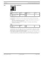
Page 194: ...Bosch Security Systems B V Torenallee 49 5617 BA Eindhoven Netherlands www boschsecurity com Bosch Security Systems B V 2019 ...

Reviews: