


PSU 5000 / PSG 3000
Instructions for Assembly and Operation
Controlling
the inverter
1070 078 224--- 108
8--3
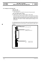
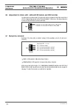
8.2 24 V weld time signal and analog input voltage
As an
option,
the inverter can be controlled by a 24 V weld time signal and an ana-
log input voltage in the range of 1 to 10 V. For this purpose, switch 8 of DIP switch
bank S1 must be set to “ON” (cf. Section 9.5). The 5 kHz firing signal (X5) and the
synchronization voltage connection (X5) must be disconnected beforehand.
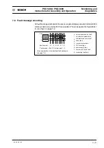
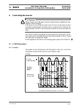
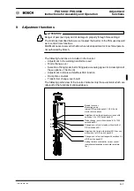
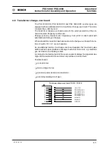
8.2.1 Function
Condition for firing
If the 24 V weld time signal is present, and if the analog input voltage has passed
the 1 V threshold, the transistors are fired.
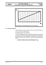
Conversion of the analog signal with respect to the current control range:
U
set
= 1.6 V
'
min. value
U
set
= 10 V
'
max. value
The weld time signal can be applied independent from the mains system, it is pro-
cessed synchronous with the internal ms cycle.
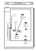
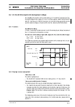
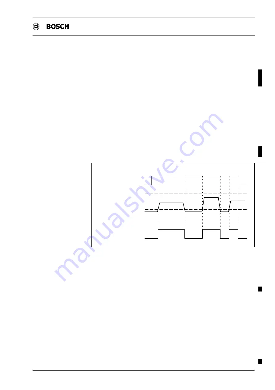
Inputs:
Weld time
+24 V
0 V
Command value max. 10V
Threshold 1 V
Transistor
firing:
On
Off
0 V
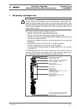
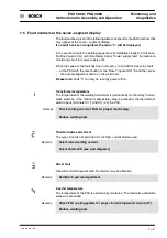
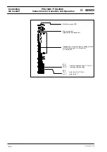
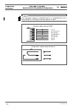
8.2.2 Displays and pin assignment
”Weld time” LED
The LED is lighted when
-- the ”weld time” signal (at X22) and an analog value > 1V are present.
”max. pulse width reached” display
The decimal point of the seven--segment display is lighted when
-- the maximum pulse width has been reached. In control operation, this display
appears only when the commanded current cannot be reached. In this case, the
inverter must have worked at the limit for at least 5 consecutive mains cycles.
Please note:
The inverter continues working despite this display. It is not
switched off!
The following partial view of the inverter indicates only those elements which are
relevant for the functions mentioned above. For further elements, please refer to
section 11.
Summary of Contents for PSG 3000 Series
Page 1: ...PSU 5000 PSG 3000 Instructions for Assembly and Operation MF Welding Inverters 109 Version ...
Page 3: ......
Page 5: ...PSU 5000 PSG 3000 Instructions for Assembly and Operation 1070 078 224 109 ...
Page 97: ...PSU 5000 PSG 3000 Connection Instructions for Assembly and Operation 1070 078 224 109 11 18 ...
Page 101: ...PSU 5000 PSG 3000 Maintenance Instructions for Assembly and Operation 1070 078 224 108 13 2 ...
Page 105: ...PSU 5000 PSG 3000 Instructions for Assembly and Operation Accessories 1070 078 224 108 14 4 ...
Page 113: ...PSU 5000 PSG 3000 Instructions for Assembly and Operation Index 1070 078 224 109 17 4 ...
Page 114: ...1070 078 224 109 98 10 GB MBA AT VWS Printed in Germany ...


