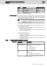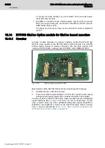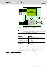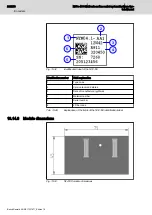
Encoder inputs assignment
Backplane pin
Description
Dig5VIn0a– , Di
Clock– and Clock+ from drive for axis0
(NY4120, NY4130, NY4140)
Dig5VIn0c– , Di
Data– and Data+ to drive for axis0
(NY4120, NY4130, NY4140)
Enc5V0
Power supply for axis0
(NY4120, NY4130, NY4140)
Dig5VIn1a– , Di
Clock– and Clock+ from drive for axis1
(NY4120, NY4130)
Dig5VIn1c– , Di
Data– and Data+ to drive for axis1
(NY4120, NY4130)
Enc5V1
Power supply for axis1
(NY4120, NY4130)
Enc#QuadA– , Enc#QuadA+
Clock– and Clock+ from drive for axis# (# = 0, 1,
2, 3, 4)
(NY4125)
Enc#QuadB– , Enc#QuadB+
Data– and Data+ to drive for axis# (# = 0, 1, 2, 3,
4)
(NY4125)
Enc5V#
Power supply for axis# (# = 0, 1, 2, 3, 4)
(NY4125)
EncGND
GND
Tab. 13-31:
Encoder inputs assignment
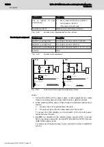
[See Note 1]
SN65HVD485
120
W
680 pF
DGND
330 pF
330 pF
A
B
EncGND
D
[See Note 3]
MAX1562
ON
Enc5V
[See Note 2]
+5V25
Dig5VIn -
NY4120 / NY4130 / NY4140
+5V25
Node
200
W
Enc
+
-
MAX1564
ON
Enc5V
EncGND
Enc
200
W
[See Note 3]
NY4125
100pF
+ 5V25
DGND
Node
SN65HVD485
A
B
[See Note 2]
[See Note 1]
not on NY4130
(*)
2k2
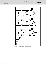
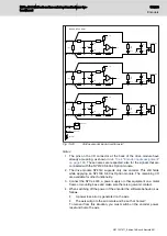
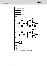
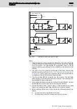
Fig. 13-23:
Input circuit for the EnDat2.2 encoder
Notes
1. Connect the NYCe 4000, a power supply or other equipment on a metal
frame or mounting base and make sure there is a galvanic contact.
2. When switching off the power of the encoder the software behavior is as
follows.
NYCe 4000 Multi-axis motion control system Hardware Sys‐
tem Manual
187/233
Encoders
R911337671_Edition 18 Bosch Rexroth AG

