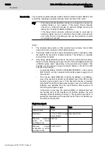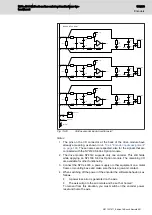
To recover from this situation, you must switch on the encoder power,
reset and home the axis.
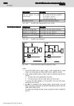
6. EncGND is connected to the internal system ground, which is ground
MCU, drive logic, analog I/O, and host PC if the MCU is NY4110 and an
IEEE 1394b cable is used.
For proper use, this ground may not be connected to motor or digital I/O
ground.
13.13 Hiperface encoder
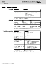
To connect the Hiperface encoder to a drive module you must install the
NY4199 SinCos Option module on the drive module. See
"NY4199 SinCos Option module for SinCos based encoders" on page 200
for detailed information.
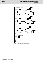
Functionally Hiperface is very similar to EnDat2.1. Main difference is that
Hiperface encoders do not produce a clock signal for the serial
communication.
In addition Hiperface encoders require a 7...11V supply voltage, depending
on the allowable cable length. For typical NYCe 4000 motion applications, a
supply of 8V is sufficient. The 8V is created on the NY4199 SinCos Option
module. The power supply can be turned on and off by the software.
The 8 V power supply can be turned on and off by software. This
functionality should be handled carefully, because the same pin of
the appropriate output is used as input for other type of encoders.
Inaccurate use can damage the encoder hardware.
Power supply
Characteristic
Specification
Main power supply
8 V ± 5% , provided by the drive module
Maximum 400 mA for 2 axes per module
Switch on/ off capability
Yes, switch on/off by software (see note 6)
●
NY4120
switch on/off per drive
●
NY4130, NY4140
switch on/off per axis
Tab. 13-40:
Power supply characteristics
Encoder data
Value
Note
Type
Hiperface
Resolution
128 lines per revolution Bosch Rexroth standard for
Hiperface encoders
Output format
-
Analog signals
Increasing direction
Clockwise
As viewed from the encoder
shaft end
Tab. 13-41:
Data of incremental encoder
196/233
Encoders
NYCe 4000 Multi-axis motion control system Hardware Sys‐
tem Manual
Bosch Rexroth AG R911337671_Edition 18

