3. Firmly connect the motor to the machine.
Fastening screws for foot assembly of IndraDyn A motors.
Motor
frame
size
Hole
⌀ [mm]
Screw 8.8
DIN EN ISO 4762
DIN EN ISO 4014
Tightening torque
M
A
[Nm] at μ
K
= 0.12
Washer DIN
EN ISO ...
100 ...
104
11
M10 x ...
48
28,738
130 ...
134
12
160 ...
164
14
M12 x ...
84
180 ...
184
14.5
200
19
M18 x ...
295
7,090
225
21
M20 × ...
415
Fig.6-2:
Fastening screws (foot mounting) tightening torque
4. Reattach the air baffles to the motor.
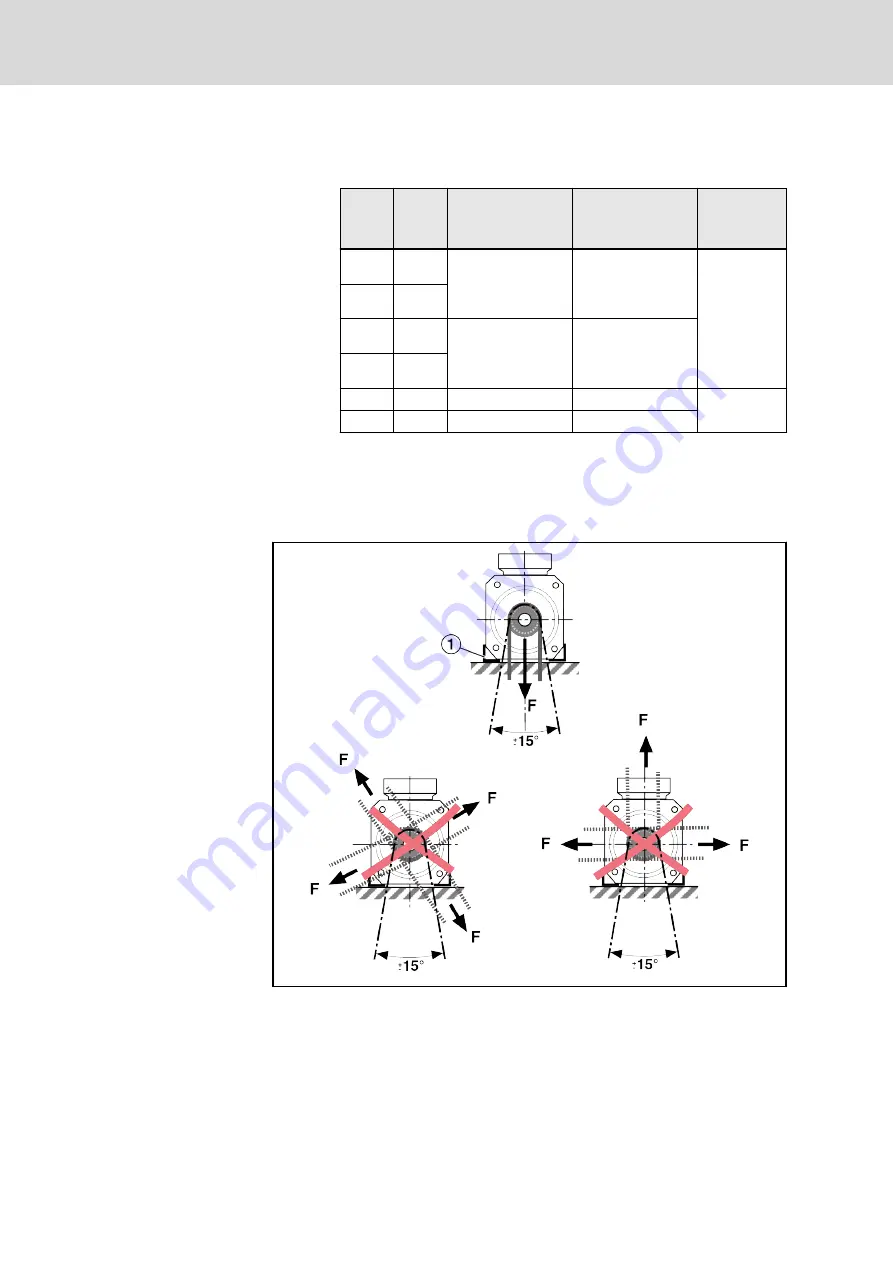
In contrast to flange assembly, radial forces may only be effective in a direc‐
tion perpendicular to the mounting surface (± 15°) if foot assembly is selec‐
ted. The transmission of forces in other effective directions is not allowed.
①
Mounting feet
Fig.6-3:
Example foot assembly
Bosch Rexroth AG
DOK-MOTOR*-2AD********-IT01-EN-P
Rexroth 2AD Asynchronous Housing Motors
32/61
Assembly
Courtesy
of
CMA/Flodyne/Hydradyne
▪
Motion
Control
▪
Hydraulic
▪
Pneumatic
▪
Electrical
▪
Mechanical
▪
(800)
426-5480
▪
www.cmafh.com


