background image


About this product 21/64


RE 92750-01-B/06.2018, A10VG, Series 10, 

Bosch Rexroth AG


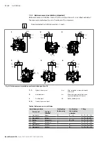
5.2.2  Functional description
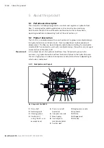
Torque and rotational speed are applied to the drive shaft (1) by a drive motor.  
The drive shaft is connected to the cylinder (11) by splines, causing the cylinder to 
rotate. With every revolution, the pistons (12) complete a stroke in the cylinder 
bores, the size of which depends on the pitch of the cradle (14). The slipper 
pads (13) are held on with the pistons and guided along the glide surface of the 
cradle by the retaining plate (2).
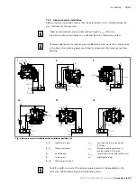
The pitch of the swashplate during a revolution causes each piston to move over the 
bottom and top dead centers and back to its initial position. During this sequence, 
hydraulic fluid is fed in and drained out through the two control slots in the control 
plate (8) according to displacement. On the high-pressure side (10), the hydraulic 
fluid is pushed out of the cylinder chamber and into the hydraulic system by the 
pistons. At the same time, hydraulic fluid flows into the expanding piston chamber 
on the low-pressure side (6). In a closed circuit, this is supported by the return flow 
and boost pressure.
The operating pressure is limited by the pressure cut-off.
The pressure cut-off corresponds to a pressure control which reduces the pump 
capacity once the set specified pressure command value is reached so that the set 
pressure is maintained but not exceeded.
The two high-pressure relief valves protect the hydrostatic transmission (pump and 
motor) from overloading. They limit the maximum pressure in the respective high-
pressure line and serve simultaneously as boost valves. High-pressure relief valves 
are not working valves and are only suitable for pressure peaks or high rates of 
pressure change.
The boost pump (7) continuously supplies a sufficient volume of fluid (boost volume) 
from a small reservoir to the low-pressure side of the closed circuit via a check valve 
to replenish the internal leakage of the variable pump and consumer.
The boost pump is an internal gear pump which is driven directly via the drive shaft.
 In order to replenish the internal leakage in the variable pump and consumers, 
depending on the size or version, the following connections must be connected to an 
external source of boost pressure:


• NG18 – port S


• NG28 and 45 – port 

G (without DA control valve)


• NG28 and 45 – port 

F

e

 (with DA control valve)


• NG63 – port F

a

The boost-pressure relief valve is integrated.
The optional sequence valve interrupts the active control pressure. The springs in 
the stroking chambers move the stroking piston (3) towards the middle position 
(neutral position). The reset function is influenced by the current working pressure 
and the rotational speed.
Switching off the control pressure does not ensure that the pump goes to the central 
position (neutral position).


Use an appropriate emergency-off device to ensure that the drive can be brought 
to a safe position at any time. The machine or system manufacturer is responsible 
for the installation of a proper emergency-off device.

Pump function

Pressure cut-off

High-pressure safeguarding

Version with boost pump

Version without boost 

pump (external boost 

pressure supply)

Sequence valve  

(optional)

Summary of Contents for Rexroth A10VG

Page 1: ...Instruction manual RE 92750 01 B 06 2018 Replaces 02 10 English Axial piston variable pump A10VG Series 10 ...

Page 2: ...concerning a certain condition or suitability for a certain application can be derived from our information The information given does not release the user from the obligation of own judgment and verification It must be remembered that our products are subject to a natural process of wear and aging The cover shows an example application The product delivered may differ from the image on the cover ...

Page 3: ...e description 20 5 2 Product description 20 5 2 1 Axial piston unit layout 20 5 2 2 Functional description 21 5 3 Bypass function 22 5 3 1 Activating and deactivating the bypass function 22 5 4 Product identification 24 6 Transport and storage 25 6 1 Transporting the axial piston unit 25 6 1 1 Transporting by hand 25 6 1 2 Transporting with a lifting device 25 6 2 Storing the axial piston unit 27 ...

Page 4: ...Testing the hydraulic fluid supply 49 8 1 3 Performing a functional test 49 8 2 Running in phase 50 8 3 Recommissioning after standstill 50 9 Operation 51 10 Maintenance and repair 51 10 1 Cleaning and care 51 10 2 Inspection 52 10 3 Maintenance 52 10 4 Repair 53 10 5 Spare parts 53 11 Removal and replacement 54 11 1 Required tools 54 11 2 Preparing for removal 54 11 3 Removal 54 11 4 Preparing co...

Page 5: ...e permissible technical data 92750 Data sheet Mineral oil based hydraulicfluids and related hydrocarbons Describes the requirements on a mineral oil basedhydraulic fluid and related hydrocarbons for operation with Rexroth hydraulic components and assists you in selecting a hydraulic fluid for your hydraulic system 90220 Data sheet Environmentally acceptable hydraulic fluids Describes the requireme...

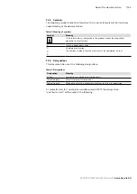
Page 6: ... damage on page 16 as well as before a sequence of actions or an instruction for action involving a risk of personal injury or property damage Always follow the instructions on avoiding the dangers associated with the use of this product Safety instructions are set out as follows Signal word Type and source of danger Consequences of noncompliance Measures to prevent danger Warning sign draws atten...

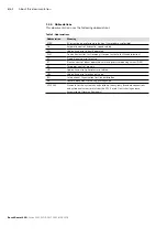
Page 7: ...to its full extent Single independent action 1 2 3 Numbered instruction The numbers indicate that the actions must be completed in order 1 3 3 Designations This documentation uses the following designations Table 4 Designations Designation Meaning A10VG Axial piston variable pump closed circuit Threaded plug Metal screw pressure resistant Protective plug Made out of plastic not pressure resistant ...

Page 8: ...es Institut für Normung German Institute for Standardization EP Proportional control electric ET Electric control direct operated with two pressure reducing valves DRE EZ Two point control electric HD Hydraulic control pilot pressure related HW Hydraulic control mechanical servo ISO International Organization for Standardization RE Rexroth document in the English language VDI 2230 Standard for the...

Page 9: ...ton unit is only approved as a pump for hydrostatic drives in closed circuit Observe the technical data the application and operating conditions and the performance limits as specified in data sheet 92750 and in the order confirmation Information about approved hydraulic fluids can be found in data sheet 92750 The axial piston unit is only intended for commercial use and not for private use Intend...

Page 10: ...rity with associated technical terms For transporting and handling the product additional familiarity with the use of lifting devices and lifting accessories is required In order to ensure safe use these activities should only be performed by skilled personnel or an instructed person under the direction and supervision of skilled personnel Skilled personnel refers to persons who possess the profes...

Page 11: ...on protection applications or in safety related parts of a control system functional safety Only commission the product if it has been determined that the end product e g machinery or system in which the Rexroth products are installed complies with the country specific provisions safety regulations and standards for the application Use tools appropriate for the work being performed and wear approp...

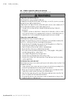
Page 12: ... or fracture or damage to the product Make sure that the load bearing capacity of the lifting device is sufficient to safely bear the weight of the axial piston unit Never stand or put your hands under a suspended load Make sure the unit remains stable during transport Wear your personal protective equipment e g safety goggles safety gloves suitable working clothes safety shoes Use suitable liftin...

Page 13: ...pected machine movements Use the manual override only for functional testing or in the event of technical malfunctions Using the manual override on a permanent basis e g by wedging blocking is not permitted The use of the manual override is only permitted with limited technical data e g 0 25 maximum data Check whether or not your machine requires additional safety measures for your application to ...

Page 14: ...they do not become kinked or twisted do not rub on edges and do not run through sharp edged ducts without adequate protection Contact with hydraulic fluid Risk of adverse health effects e g eye injury skin irritation poisoning from inhalation Avoid contact with hydraulic fluids When working with hydraulic fluids strictly follow the safety instructions provided by the lubricant manufacturer Wear yo...

Page 15: ...eries 10 Bosch Rexroth AG 2 7 Personal protective equipment Personal protective equipment is the responsibility of the user of the axial piston unit Observe the safety regulations in your country All pieces of personal protective equipment should be intact ...

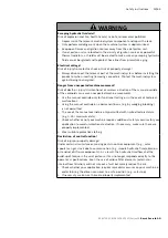
Page 16: ...oyed Never operate the axial piston unit with insufficient hydraulic fluid Specifically make sure the rotary group has sufficient lubrication When commissioning a machine system make sure that the housing area and the working lines of the axial piston unit are filled with hydraulic fluid and remain filled during operation Avoid air inclusions in the forward drive shaft bearing especially with the ...

Page 17: ...id particle contamination and water in the hydraulic system Improper cleaning Product can be damaged Close all openings with appropriate protective covers in order to prevent cleaning agents from entering the hydraulic system Never use solvents or corrosive cleaning agents Use only water and if necessary a mild cleaning agent to clean the axial piston unit Do not point a high pressure cleaner at s...

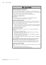
Page 18: ...bserve the safety data sheet for the hydraulic fluid and the specifications provided by the system manufacturer Danger from hot components Nearby products can be damaged Components which heat up e g solenoids can cause damage to nearby products if they are too close during installation When installing the axial piston unit check the distances to nearby products to ensure that they are not damaged ...

Page 19: ... Fig 1 Axial piston unit The scope of delivery includes the following Axial piston unit as per order confirmation The following parts come assembled on the unit Protective covers 1 Protective plug threaded plugs 2 Connector protective covers 3 For version with through drive protective cover and mounting bolts 4 ...

Page 20: ... The flow can be continuously adjusted by controlling the swashplate cradle 14 For axial piston units with swashplate design the pistons are arranged axially relative to the drive shaft In the closed circuit the hydraulic fluid flows from the hydraulic pump to the consumer e g hydraulic motor and from there directly back to the hydraulic pump There is a high pressure side and a low pressure side w...

Page 21: ...m overloading They limit the maximum pressure in the respective high pressure line and serve simultaneously as boost valves High pressure relief valves are not working valves and are only suitable for pressure peaks or high rates of pressure change The boost pump 7 continuously supplies a sufficient volume of fluid boost volume from a small reservoir to the low pressure side of the closed circuit ...

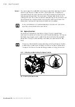
Page 22: ...rdingly Various control devices are available depending on requirements Information about them can be found in data sheet 92750 5 3 Bypass function For vehicles with hydrostatic travel drive as long as there is no downstream mechanical interruption of the drive train switch to idle freewheeling the flow can be altered using a bypass circuit in order to tow the vehicle out of the immediate danger z...

Page 23: ...lead to excessive heat generation and inadequate lubrication This will overheat and damage the axial piston unit Wear heat resistant protective clothing e g gloves Only tow the vehicle out of the immediate danger zone Notice Draining of the hydraulic circuit Risk of damage While towing with the bypass function activated the closed hydraulic circuit drains itself This can result in unintended funct...

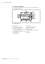
Page 24: ...hingen Made in Germany A10VG45HW1 10R NSC10F003S R90XXXXXXX SC X 12345678 18W19 n XXXX min 1 P XXX kW m XXX kg 7202 Fig 4 A10VG name plate 1 Manufacturer 2 Internal plant designation 3 Sample category optional 4 Direction of rotation viewed on drive shaft here clockwise 5 Designated area for inspection stamp 6 Weight optional 7 Power optional 8 Bar code 9 Rotational speed optional 10 Manufacturing...

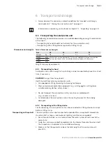
Page 25: ...ted by hand for a short time if necessary Caution Danger from heavy loads Health hazard from carrying axial piston units Use appropriate lifting lowering and moving techniques Wear your personal protective equipment e g safety goggles safety gloves suitable working clothes safety shoes Do not transport the axial piston unit by sensitive assembled parts e g sensors or valves Carefully place the axi...

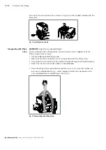
Page 26: ... and cause injury Use the widest possible lifting strap Make sure that the axial piston unit is securely fixed with the lifting strap Only guide the axial piston unit by hand for fine positioning and to avoid swinging Never stand or put your hands under a suspended load Place the lifting strap around the axial piston unit in such a way that it does not pass over assembled parts e g valves piping a...

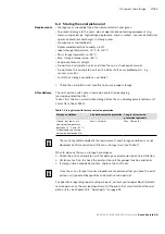
Page 27: ...ible storage times for an unpackaged axial piston unit as per Data Sheet 90312 Table 7 Storage time with factory corrosion protection Storage conditions Standard corrosion protection Long term corrosion protection optional Closed dry room at a consistent temperature between 5 C and 20 C Undamaged and sealed corrosion protection film Max 12 months Max 24 months The warranty will be voided if the re...

Page 28: ...apter 10 1 Cleaning and care on page 51 2 Drain the axial piston unit 3 For storage times up to 12 months Coat the inside of the axial piston unit with mineral oil and fill with about 100 ml of mineral oil For storage times up to 24 months Fill the axial piston unit with VCI 329 corrosion protection 20 ml Filling is done through the drain port T1 or T2 see chapter 7 4 Installing the axial piston u...

Page 29: ...rom the axial piston unit Check the axial piston unit for transport damage and completeness see chapter 4 Scope of delivery on page 19 Dispose of the packaging in accordance with the regulations in your country 7 2 Installation conditions The installation position and location of the axial piston unit essentially determine how it is installed and commissioned such as when filling and air bleeding ...

Page 30: ...luid level under all operating conditions This will prevent air from being drawn in and foam from forming When designing the reservoir ensure that there is adequate distance between the suction line and the drain line This prevents the heated return flow from being drawn directly back into the suction line Make sure that a minimum suction pressure of 0 8 bar absolute is present at port S 0 5 bar a...

Page 31: ...7 3 Installation position The axial piston unit can be installed in the following positions The pipeline routing shown illustrates the basic layout If filling the stroking chambers via X1 and X2 is not possible in the final installation position then fill before installation e g in installation position 2 In order to prevent unexpected actuation and damage the stroking chambers must be air bled If...

Page 32: ...2 X2 SB ht min hmin X1 Fig 8 Below reservoir installation with installation position 1 6 T1 T2 Highest drain port ht min Min required immersion depth 200 mm R Air bleed port hmin Minimum required distance to reservoir bottom 100 mm S Suction port SB Baffle baffle plate X1 X2 Control pressure port Table 8 Below reservoir installation Installation position Air bleeding the housing Air bleeding the s...

Page 33: ... 11 12 T2 F2 S R SB ht min hmin hS max F1 X1 X2 T1 T2 T1 S F2 ht min hmin F1 hS max SB X1 X2 T2 T1 S F2 SB ht min hmin hS max F1 X1 X2 T2 S R F2 SB ht min hmin 0 5 bar hS max F1 X1 X2 X1 T1 X2 S F2 SB ht min hmin hS max F1 X2 S F2 SB ht min hmin hS max F1 T2 X1 Fig 9 Above reservoir installation with installation position 7 12 T1 T2 Highest drain port ht min Min required immersion depth 200 mm F1 ...

Page 34: ...ls in the order confirmation If the material number for the axial piston unit does not match the one in the order confirmation contact your local contact person for clarification You can find their contact information under www boschrexroth com addresses 3 Before installing completely drain the axial piston unit to prevent mixing with the hydraulic fluid used in the machine system 4 Check the dire...

Page 35: ... their pretensioning after just a short operating time An automatic clamping device can lessen the speed variations and vibrations and thus avoid subsequential damage When using drives with toothed belts or V belts always use an automatic clamping device On the drive of an axial piston unit a cardan shaft may cause vibrations and excessive rotary angular acceleration Depending on the frequency and...

Page 36: ...y the coupling manufacturer Do not fasten down the axial piston unit until the coupling has been correctly installed 6 Fasten the axial piston unit at the installation location 7 Align the drive shaft of the axial piston unit and the output shaft of the drive motor so there is no angular deviation 8 Make sure no excessive axial and radial forces are acting on the drive shaft 9 For bell housing ins...

Page 37: ... the drive shaft of the axial piston unit 4 Bring the axial piston unit to the installation position and fasten it If necessary details on the required tools and tightening torque for the mounting bolts can be obtained from the system manufacturer 7 4 7 Completing installation 1 Remove any installed transport screws Caution Operation with protective plugs Operating the axial piston unit with prote...

Page 38: ...eries 10 on page 43 Failure to do so could lead to malfunctions or damage If a port is not being used plug it with a threaded plug since the protective plugs are not pressure resistant Setting screws are protected against unauthorized adjustment by tamper proof caps Removal of the tamper proof caps will void the warranty If you need to change the settings please contact your local contact person Y...

Page 39: ... it back down 3 Tighten the mounting bolt 1 again Tightening torque MA 6 5 Nm 1 2 1 2 Fig 12 Changing the lever position of the HW control 7 4 9 Changing the lever position of the DA control valve size 28 to 63 If necessary you can change the position of the lever by turning Required tools Hexagon socket wrench with WAF 4 mm 1 Loosen the clamping screw 1 of the DA lever 2 2 Turn the DA lever to th...

Page 40: ...s 10 on page 43 The machine system manufacturer should make sure the connecting elements and lines correspond to the specified application conditions pressure flow hydraulic fluid temperature with the necessary safety factors Connect only hydraulic lines that are appropriate for the axial piston unit port pressure level size system of units Observe the following information when routing the suctio...

Page 41: ... the Anglo American inches system of units Various kinds of seals are also used The system of units the kind of seal and the size of female thread and stud ends e g threaded plug must all match There is a risk of confusion due to the limited ways of visually telling them apart Warning Leaky or bursting stud ends For fittings if a stud end that does not match the system of units kind of seal and si...

Page 42: ...0 A10VG RE 92750 01 B 06 2018 G S PS T1 R X1 X2 MB MA T2 B A Fig 14 Port overview size 18 S B A T1 T2 MA MB G R X1 X2 Fe PS Fig 15 Port overview sizes 28 and 45 R X1 X2 Fe Fa Y2 PS MB G MA T2 T1 Y1 B A S Fig 16 Port overview size 63 Port overview ...

Page 43: ...lugged in normal operation 4 Plugged for external boost pressure supply size 28 to 63 5 Depending on the installation position T1 or T2 must be connected see chapter 7 3 Installation position on page 31 6 For size 28 and 45 port G serves as boost pressure port inlet Fa and must be connected for filtration in the pressure line 7 Only available on version with pressure cut off 8 Must be connected fo...

Page 44: ... apply when the plugs are dry or lightly oiled 2 The tightening torques for the threaded plugs apply when the plugs are dry when lightly oiled the tightening torques for M10 1 are reduced to 10 Nm and to 17 Nm for M12 1 5 To connect the axial piston unit to the hydraulic system 1 Remove the protective plugs or threaded plugs from the ports where the connections should be made according to the hydr...

Page 45: ...ails on the connector type of protection and matching mating connector can also be found in data sheet 92750 The mating connector is not included in the scope of delivery 1 Switch off the power supply to the relevant system component 2 Electrically connect the axial piston unit 12 or 24 V Before connecting check whether the connector protective covers 3 are off see Fig 11 Removing transport protec...

Page 46: ...m Bosch Rexroth recommends a flushing cycle for the entire system before initial commissioning To avoid internal contamination do not include the axial piston unit in the flushing cycle Use an additional flushing unit to perform the flushing cycle Follow the instructions of the flushing unit s manufacturer for the exact procedure during the flushing cycle ...

Page 47: ... within the operator s reach Always follow the instructions of the machine system manufacturer during commissioning CAUTION Commissioning an improperly installed product Risk of injury and property damage Make sure all electrical and hydraulic ports are connected or plugged Only commission a completely installed fully functioning product with original accessories from Bosch Rexroth 8 1 Initial com...

Page 48: ... the axial piston unit to collect any hydraulic fluid that may leak Notice Contaminated hydraulic fluid The cleanliness levels of commercial hydraulic fluid are usually insufficient for our components Use a suitable filter system to filter hydraulic fluids during filling to minimize solid particle contamination and water in the hydraulic system 2 Fill and air bleed the axial piston unit via the ap...

Page 49: ...nd can withstand the max pressure 5 Check the suction pressure at port S of the axial piston pump at nominal speed and max swivel angle Refer to data sheet 92750 for the permissible value 6 At maximum working pressure check the case drain pressure at port T1 or T2 Refer to data sheet 92750 for the permissible value 8 1 3 Performing a functional test WARNING Improperly connected axial piston unit M...

Page 50: ...and mechanical hydraulic efficiency is also greater until the running in phase of about 10 operating hours is concluded To ensure that contamination in the hydraulic system does not damage the axial piston unit Bosch Rexroth recommends the following after the running in phase After the running in phase have a hydraulic fluid sample analyzed for the required cleanliness level Change the hydraulic f...

Page 51: ...ntervals described in this manual 10 1 Cleaning and care NOTICE Damage to seals and electrical system due to mechanical effects The jet of a high pressure cleaner may damage the seals and electrical system of the axial piston unit Do not point a high pressure cleaner at sensitive components e g shaft seal electrical connections and components For cleaning and care of the axial piston unit observe ...

Page 52: ...on unit and system clean Daily Check axial piston unit for unusual noise development Daily Check fastening elements for tight seating All fasteners have to be checked when the hydraulic system is switched off depressurized and cooled down Monthly 10 3 Maintenance The axial piston unit is low maintenance when used as intended The service life of the axial piston unit is heavily dependent on the qua...

Page 53: ...are parts Spare parts that do not meet the technical requirements specified by Bosch Rexroth can cause injury and property damage Only use original spare parts from Rexroth to repair the Rexroth axial piston units otherwise the functional reliability of the axial piston unit cannot be guaranteed and the warranty will be voided The spare parts lists for axial piston units are order specific When or...

Page 54: ...as follows to remove the axial piston unit 1 Make sure you have the appropriate tools and wear personal protective equipment 2 Allow the axial piston unit to cool down until it can be removed without danger 3 For below reservoir installation before removing the axial piston unit from the entire system seal the connection to the reservoir or drain the reservoir 4 Place a drip tray under the axial p...

Page 55: ...xial piston unit into its constituent parts for proper recycling 5 For example separate the parts into Castings Steel Aluminum Non ferrous metal Electronic waste Plastic Seals 13 Extension and conversion Do not modify the axial piston unit or its assembled parts Changes to settings on the customer side should only be made using the product specific setting instructions The warranty from Bosch Rexr...

Page 56: ...ow your product works in conjunction with the entire system Try to find out whether or not the product was working properly in conjunction with the entire system before the fault occurred Try to determine any changes to the entire system in which the product is installed Were there any changes to the product s application conditions or operating range Has maintenance work recently been carried out...

Page 57: ...lter as necessary Drive speed too high Machine system manufacturer Reduce drive speed Wrong direction of rotation Machine system manufacturer Check correct direction of rotation see chapter 7 4 1 Preparation on page 34 Improper mounting of the axial piston unit Check the mounting of the axial piston unit according to the specifications of the machine system manufacturer observe tightening torques ...

Page 58: ...lter too small or blocked etc Machine system manufacturer Check the system e g optimize inlet conditions use suitable hydraulic fluid Fill the suction line with hydraulic fluid Remove foreign particles from the suction line Check the filter system and change the filter as necessary Hydraulic fluid not in optimal viscosity range Machine system manufacturer Check temperature range and use suitable h...

Page 59: ... etc Machine system manufacturer Check the system e g optimize inlet conditions use suitable hydraulic fluid Fill the suction line with hydraulic fluid Remove foreign particles from the suction line Check the filter system and change the filter as necessary Hydraulic fluid not in optimal viscosity range Machine system manufacturer Check temperature range and use suitable hydraulic fluid Insufficie...

Page 60: ...ng and control valves in the axial piston unit boost pressure relief valve high pressure relief valve pressure cut off pressure reducing valve Air bleed the axial piston unit and hydraulic system Contact Bosch Rexroth Service Unstable control signal Contact machine system manufacturer or Bosch Rexroth Service Malfunction in the control devices or the controller Contact Bosch Rexroth Service Excess...

Page 61: ...l piston unit can be found on the data sheet 92750 The data sheet can be found online at www boschrexroth com mediadirectory You can find further information in the Mobile Hydraulics online product catalog www boschrexroth com axial piston pumps Order related technical data for your axial piston unit can be found in the order confirmation ...

Page 62: ...f rotation 34 Disassembly 54 Performing 54 Preparing 54 Disposal 55 Drive shaft 20 E Eye bolt 25 F Filling 48 Flushing cycle 46 Functional description Control 22 Functional test 49 H High pressure safeguarding 21 High pressure side 20 I Identification 24 Inspection 52 Installation 29 34 Completing 37 General instructions 35 On a gearbox 36 On gearbox 36 Preparation 34 With cardan shaft 37 With cou...

Page 63: ...3 Replacement 54 Required documentation 5 Retaining plate 20 Running in phase 50 S Safety instructions 9 General 11 Product specific 12 Signal word 6 Scope of delivery 19 Slipper pad 20 Solenoid position Changing 45 Spare parts 53 Storage 25 Storage time 27 Storing 27 Stroking piston 20 Suction port 20 Symbols 7 T Technical data 61 Tightening torques 43 Tool 54 Transportation 25 By hand 25 With ey...

Page 64: ...straße 4 89275 Elchingen Germany Phone 49 7308 82 0 info ma boschrexroth de www boschrexroth com Subject to change Printed in Germany RE 92750 01 B 06 2018 Your local contact person can be found at www boschrexroth com addresses ...

Reviews: