Installation
27/56
RE 93223-01-B/09.2020, A21VG Series 10, Bosch Rexroth Corporation
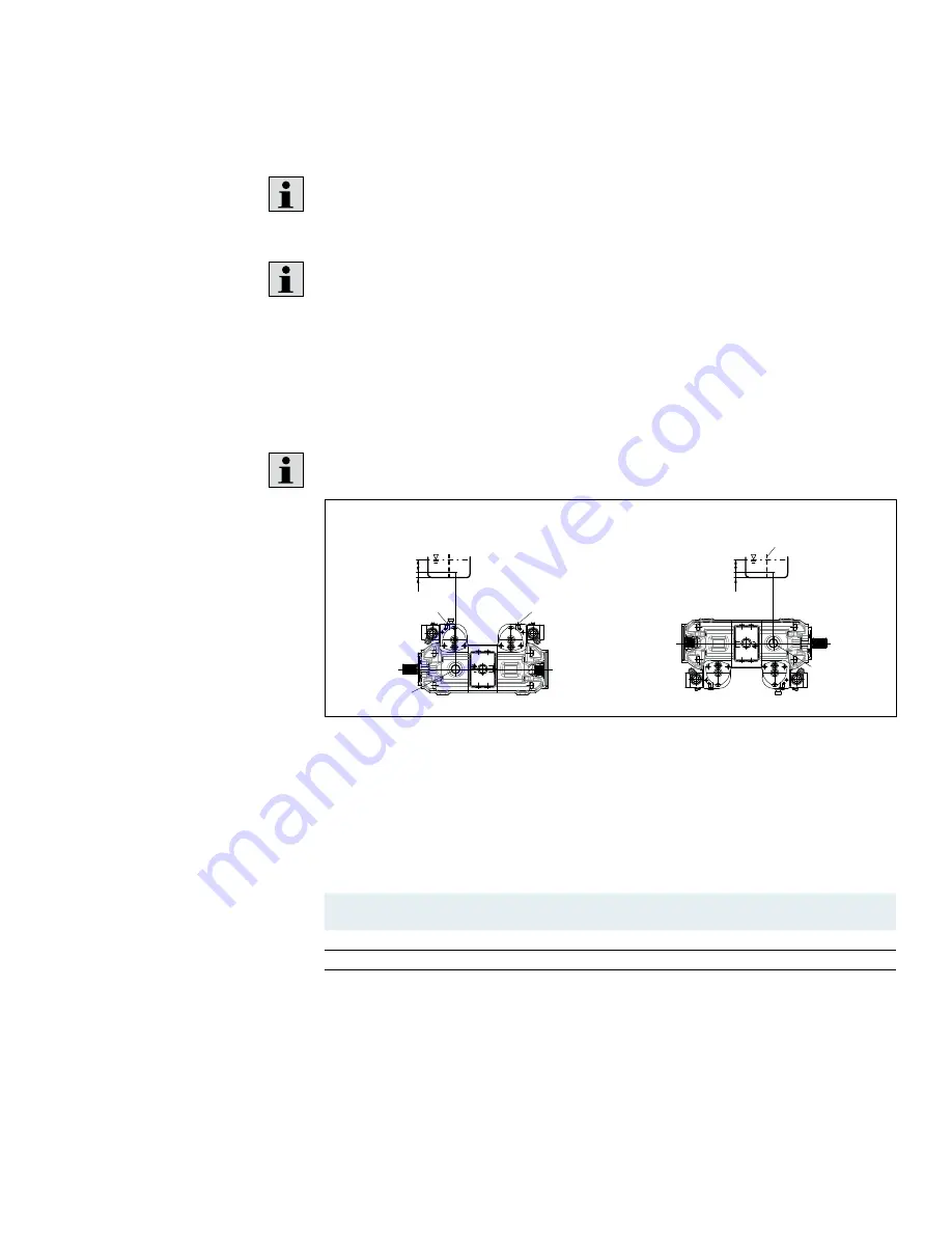
7.3 Installation position
The following installation positions are permissible. The shown piping layout
illustrates the basic layout.
If it is not possible to fill the stroking chambers via
X
1
to
X
2
in the final
installation position, this must be done prior to installation.
In order to prevent unexpected activation behavior and damage, the stroking
chambers must be air bled via ports
X
1
,
X
2
, according to their installation
position.
7.3.1
Below-reservoir installation (standard)
Below-reservoir installation means that the axial piston unit is installed outside of
the reservoir below the minimum fluid level.
Recommended installation position: 1 and 2 (without boost pump)
1
2
T
X
1
, X
2
X
2
, R, X
1
h
t min
h
min
SB
T
h
t min
h
min
SB
Fig. 6: Below-reservoir installation A21VG without boost pump, installation position 1–2
R
Air bleed port
h
t min
Minimum required immersion depth
(200 mm)
T
Reservoir port (case drain)
SB
Baffle (baffle plate)
h
min
Minimum required spacing to
reservoir bottom (100 mm)
Table 8: Below-reservoir installation
Installation position
Air bleeding the
housing
Air bleed
Stroking chamber
Filling
1 (drive shaft, horizontal)
R*
X
1
, X
2
T + X
1
+ X
2
2 (drive shaft, horizontal)
–
–
T
* If R port is inaccessible, for installation position 1, the X
1
and X
2
ports can be opened to bleed
the air when the unit is not in use. Does not apply to HT units.


