26/104 About this product
Bosch Rexroth AG
, A4... with HS5E pilot control valve/Series 3x, RE 92076-01-B/10.2017
parameter of the pump switching logic using different characteristic curves and
functions in the pump manipulated variable adaptation. The system passes on the
output parameter as a valve command value to the valve controller.
5.3.2 Cascading control structure
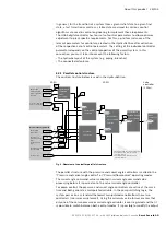
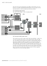
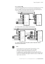
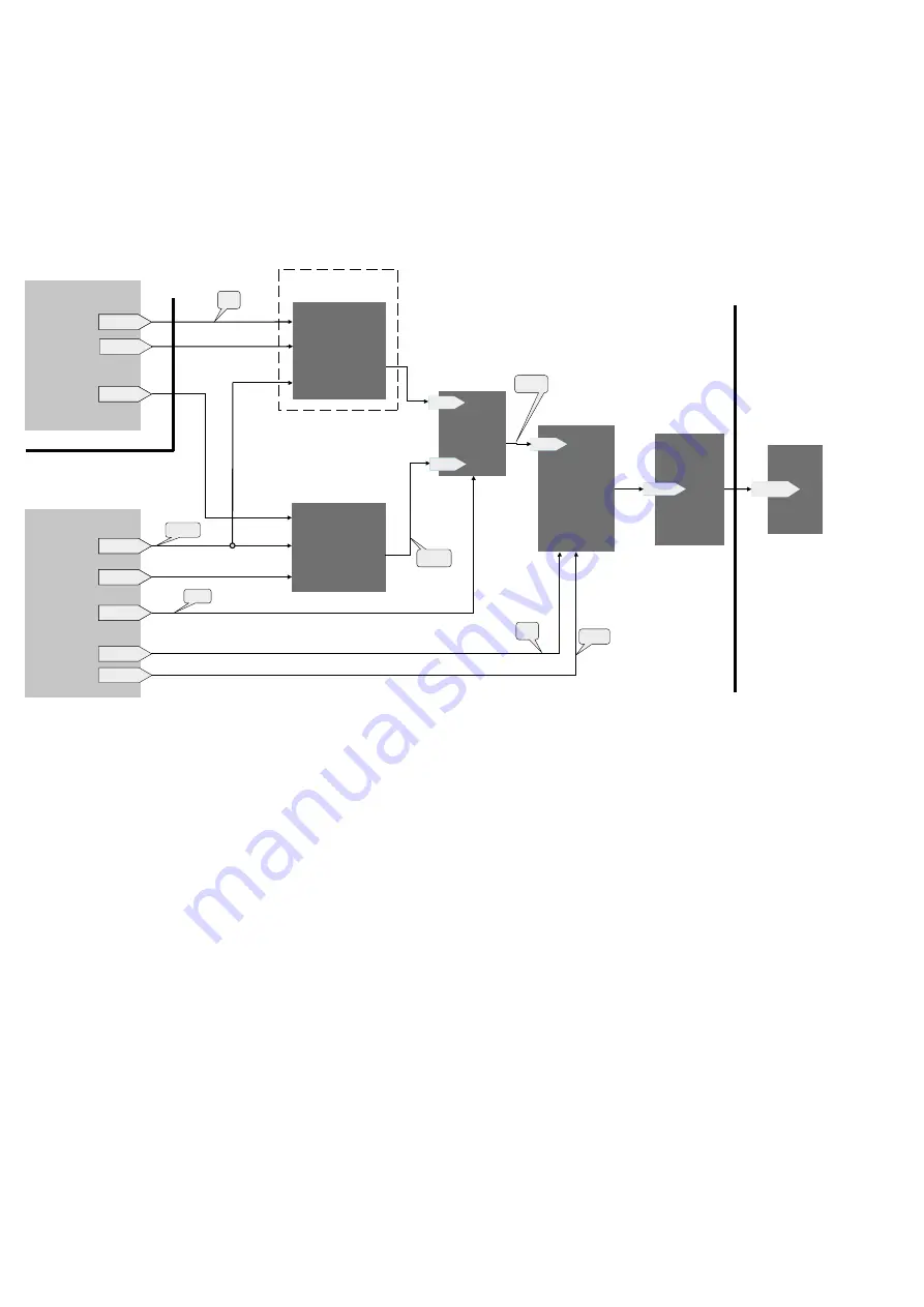
The control structure below is used in the HydraulicDrive:
Fig. 4: Overview of controller cascade structure
The cascade structure with the pressure and swivel angle controllers is called in the
“Pressure and swivel angle control” or “Pressure/flow control” operating modes.
The system offsets the swivel angle command value in swivel angle command value
processing with different variables. The outputs of swivel angle command value
processing and of the pressure controller are passed on to the switching logic. In
the switching logic, the system forms the swivel angle command value that is valid
for control. In actual pressure value acquisition, the system compares the different
actual pressure values and generates from them the resulting sign for the switching
logic. The output of the swivel angle controller is passed on to the manipulated
variable adjustment of the swivel angle controller.
P-0-2992
P-0-2914
P-0-2957.06
S-0-0882
S-0-0809
P-0-2972
P-0-2803
[%]
[%]
SW [%]
[bar]
SW [%]
[%]/s
[bar]/s
P-0-2958.0.1
P-0-2951 Bit 9
P-0-2986
P-0-2952
P-0-2836
P-0-2837
XREG
VREG
IREG
Swivel angle
command value
controller
Torque limitation
of pump
Swivel angle
command value
processing
Pressure
controller
Working line of
actual pressure
value
Pressure sign
Working line of
actual swivel
angle value
Actual pressure
value
Actual swivel angle
value
Pressure command
value of controller
Actual value acquisition
Generator
Changeover
logic of
cascade
Swivel angle
controller
Valve
controller
Manipulated
variable
adjustment

