background image

60/104 Commissioning

Bosch Rexroth AG

, A4... with HS5E pilot control valve/Series 3x, RE 92076-01-B/10.2017

8  Commissioning

 WARnInG

Danger while working in the danger zone of a machine/system!

Danger to life or risk of injury or serious injury!


Pay attention to and eliminate potential danger sources before operating the 
axial piston unit.


Make sure no one is in the danger zone of the machine/system.


The emergency stop button for the machine/system must be within the 
operator’s reach.


Always follow the instructions of the machine/system manufacturer during 
commissioning.

 CAUTIOn

Commissioning an improperly installed product!

Risk of injury and property damage!


Make sure that all the electrical connections and hydraulic ports are connected 
or plugged correctly.


Only commission a completely installed, fully functioning product with original 
accessories from Bosch Rexroth.

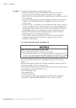
NOTICE

Missing seals and plugs lead to noncompliance with the protection class!

Fluids and foreign particles can penetrate and damage the product.


Prior to commissioning make sure that all seals and connectors are tight.

Lack of hydraulic fluid!

Inadequate amounts of hydraulic fluid can destroy the product.


Make sure that the housing of the HS5E control system is filled with hydraulic 
fluid at commissioning and during operation. Do this in the case of relatively 
long standstill periods too, since the HS5E control system can drain through the 
hydraulic lines.

Penetrating contaminants!

Damage to the HS5E control system! Any contamination of the hydraulic fluid leads 
to wear and malfunctions. Foreign particles like welding beads or metal cuttings  
in the hydraulic lines, for example, can damage the HS5E control system.


Ensure the utmost cleanliness during commissioning. 


Make sure that no contaminants penetrate when sealing the measuring ports.

Summary of Contents for REXROTH A4 Series

Page 1: ...Instruction manual RE 92076 01 B 10 2017 Replaces English Axial piston variable pump A4 with HS5E pilot control valve Series 10 11 and Series 3x ...

Page 2: ...concerning a certain condition or suitability for a certain application can be derived from our information The information given does not release the user from the obligation of own judgment and verification It must be remembered that our products are subject to a natural process of wear and aging The cover shows an example application The product delivered may differ from the image on the cover ...

Page 3: ... description 23 5 2 1 Layout of the axial piston unit 23 5 2 2 Functional description 23 5 3 Parallel and cascade control of the HS5E control system 24 5 3 1 Parallel control structure 25 5 3 2 Cascading control structure 26 5 3 3 Controller parameters parallel 27 5 3 4 Control parameter sets 27 5 3 5 Special operating modes 27 5 3 6 Working pressure limits 28 5 4 Ambient conditions 29 5 4 1 Oil i...

Page 4: ...onic components 55 7 6 2 Connection to the swivel angle sensor 56 7 6 3 X2M1 and X2M2 Analog configurable pressure sensor interface coding A M12 5 pin socket 56 7 6 4 X7E1 and X7E2 Plug in connector assignment for Ethernet port coding D M12 4 pin socket 56 7 6 5 LED status indicators 57 7 6 6 Voltage supply of the HS5E pilot control valve 57 7 6 7 Selection installation location and installation d...

Page 5: ...emoval 85 11 4 Preparing the components for storage or further use 85 12 Disposal 86 13 Extension and conversion 86 14 Troubleshooting 87 14 1 How to proceed with troubleshooting 87 14 2 Error diagnosis memory 88 14 2 1 Fault diagnosis 88 14 3 Malfunction table 89 14 3 1 Swivel angle measurement check 95 15 Technical data 96 15 1 Electrical connection of the pilot valve 96 15 2 Environmental compa...

Page 6: ...lot control valve Order confirmation Installation drawing Contains the outer dimensions all ports and the hydraulic circuit diagram for your axial piston variable pump A4 with HS5E pilot control valve Please request the installation drawing from your contact at Bosch Rexroth Installation drawing Axial piston variable pump A4 with HS5E pilot control valve Series 3x Contains the permissible technica...

Page 7: ...vation 90312 Data sheet Installation commissioning and maintenance of hydraulic systems 07900 Data sheet Rexroth HydraulicDrive functions firmware and software descriptions 30338 FK Functional description Pressure transducer with integrated electronics Type HM 20 30272 MON Assembly Instructions Installation commissioning and maintenance of hydraulic systems 07900 Data sheet Declaration of environm...

Page 8: ... word Meaning DANGER Identifies a dangerous situation that will result in death or serious injuries if it is not avoided WARNING Identifies a dangerous situation that may result in death or serious injuries if it is not avoided CAUTION Identifies a dangerous situation that may result in minor to moderate injuries if it is not avoided NOTICE Property damage The product or the environment may get da...

Page 9: ... valve 1 3 4 Abbreviations This documentation uses the following abbreviations Table 5 Abbreviations Abbreviation Meaning ATEX EC directive on explosion protection Atmosphère explosible DB Pressure relief valve PT Pressure Transducer EMC Electromagnetic compatibility GND Ground n c Not connected p Pressure character in formulas PC Personal Computer PCV Precompression Volume pDiff Control differenc...

Page 10: ...accordance with the Machinery Directive This product is intended for the following use The pressure flow control system is for control of the electrohydraulic pressure and swivel angle of an axial piston variable pump Observe the technical data operating conditions and performance limits as specified in the data sheet and order confirmation The HS5E control system is a piece of technical work equi...

Page 11: ...essure specified on the data sheet cannot be exceeded If you do not comply with the domestic EMC regulations for the present application If you need information about EMC compliant installation refer to Bosch Rexroth s EMC test documentation see chapter Electrical connection of the pilot valve on page 96 Ensuring compliance with the limit values required by national regulations is the responsibili...

Page 12: ...me Only use genuine Rexroth accessories and spare parts to ensure there is no hazard to persons due to unsuitable spare parts Observe the technical data and ambient conditions specified in the product documentation If unsuitable products are installed or used in applications that are of relevance to safety unexpected operating conditions may occur in the application which could result in injury to...

Page 13: ...l valve Series 3x Bosch Rexroth AG interference Other behavior can result when a modulated direct current e g PWM signal is applied Potential electromagnetic interference for persons e g persons with a pacemaker and other components must be tested by the machine manufacturer ...

Page 14: ...r property damage Improper transportation may cause the axial piston unit to fall down and lead to injuries e g crushing or broken bones or damage to the product Make sure that the load bearing capacity of the lifting device is sufficient to safely bear the weight of the axial piston unit Never stand or put your hands under a suspended load Make sure the unit remains stable during transport Wear y...

Page 15: ... unexpected machine movements Use the manual override only for functional testing or in the event of technical malfunctions Using the manual override on a permanent basis e g by wedging blocking is not permitted The use of the manual override is only permitted with limited technical data e g 0 25 maximum data Check whether additional protective measures are necessary for the application on your ma...

Page 16: ...onnectors Always lay cables and lines in such a way that no one can trip over them that they do not become kinked or twisted do not rub on edges and do not run without adequate protection through sharp edged ducts Contact with hydraulic fluid Risk of adverse health effects e g eye injury skin irritation poisoning from inhalation Avoid contact with hydraulic fluids When working with hydraulic fluid...

Page 17: ...ue to electromagnetic radiation Uncontrolled movements in the system The hydraulic unit with its electronic components can interfere with other electronics systems by emitting electromagnetic radiation Apart from this hydraulic units with electronic components can be interfered with by the electromagnetic radiation of other electronics systems and magnetic fields In both cases this can lead to unc...

Page 18: ...E 92076 01 B 10 2017 2 7 Personal protective equipment Personal protective equipment is the responsibility of the user of the axial piston unit with HS5E control system Observe the safety regulations and provisions in your country All pieces of personal protective equipment must be intact ...

Page 19: ...ubrication Damage or destruction of product possible Never operate the axial piston unit with insufficient hydraulic fluid Specifically make sure that the rotary group has sufficient lubrication When commissioning a machine system make sure that the housing area and the working lines of the axial piston unit are filled with hydraulic fluid and remain filled during operation Air inclusions in the f...

Page 20: ...tion may enter the ports when they are plugged Before commissioning make sure that all hydraulic connections are tight and that all of the seals and plug in connections are installed correctly to ensure that they are leak proof and fluids and foreign particles are prevented from penetrating the product Use a suitable filter system to filter hydraulic fluid during filling to minimize solid particle...

Page 21: ...llution and contamination of ground water Always place a drip tray under the axial piston unit when filling and draining the hydraulic fluid Use an oil binding agent if hydraulic fluid is spilled Observe the parameters in the safety data sheet for the hydraulic fluid and the specifications provided by the system manufacturer Danger from hot components Nearby products can become damaged Components ...

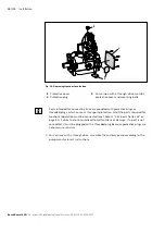
Page 22: ...of delivery includes the following Axial piston unit with HS5E P control system as per order confirmation The following parts are also assembled prior to delivery Transport protection of the drive shaft with keyed shafts 1 Protective covers 2 Protective plug threaded plug 3 For version with optional through drive closed with fail safe cover 4 HS5E pilot control valve 5 Swivel angle sensor 6 Pressu...

Page 23: ... reservoir to the variable pump and is transported from there to the consumer via a directional valve From the consumer the hydraulic fluid flows back to the reservoir via the directional valve 5 2 1 Layout of the axial piston unit 3 4 2 1 Fig 2 Cutaway diagram of A4VSO HS5E 1 HS5E control system 2 Stroking piston 3 Swashplate 4 Swivel angle sensor 5 2 2 Functional description An electrically actu...

Page 24: ...ressure present the pump swivels in the following cases Standard version A4VSO to swivel angle α 0 Vg min Standard version A4VSG to swivel angle α 100 5 3 Parallel and cascade control of the HS5E control system The pump controller has two different control structures It is possible to switch between them using pump controller control word P 0 2950 pump controller control word bit 15 Setting bit 15...

Page 25: ...angle command value is adapted in swivel angle command value processing before it is passed on to the actual swivel angle controller For pump control the pressure and swivel angle controllers are active at the same time and both generate a manipulated variable In the pump switching logic the system passes on as standard the lowest manipulated variable from these two controllers minimum value forme...

Page 26: ...troller are passed on to the switching logic In the switching logic the system forms the swivel angle command value that is valid for control In actual pressure value acquisition the system compares the different actual pressure values and generates from them the resulting sign for the switching logic The output of the swivel angle controller is passed on to the manipulated variable adjustment of ...

Page 27: ...in 2 negative P 0 2966 Pressure controller deviation positive threshold P 0 2967 Pressure controller deviation negative threshold P 0 2968 5 3 4 Control parameter sets For the HS5E you have the option of configuring and using up to four different parameter sets Using these parameter sets it is possible to optimize the control behavior of the HS5E to different connected oil volumes 5 3 5 Special op...

Page 28: ... is not exceeded The working pressure that is stated in the data sheet must not be exceeded With external pilot oil supply the HS5E pump runs independently of the actual high pressure circuit which makes possible actual adjustment independently of the working pressure in the range from 0 to 100 with A4VSO and 100 with A4VSG change of flow direction With a de energized proportional valve and a cloc...

Page 29: ...E control systems that have the F option see type code of data sheet 92050 In the case of an application with HFC fluid be aware that the service life of the HS5E control system is reduced compared to the standard application This is due to the reduced lubricity of the HFC fluid There are separately available commissioning regulations for pump systems when using HFC fluids RE 92053 amongst others ...

Page 30: ... some special applications we recommend using a pulsation damper for operation Due to the reduction in the pressure pulsation that is typical of pumps this also positively affects the noise level of the hydraulic system You can find information about this in data sheet RE 50142 5 7 Master slave operation Pressure p Q p U i Swivel angle Setpoint value MASTER Slave 1 Slave n αactual αset αset Fig 5 ...

Page 31: ... circuitry for analog master slave operation Fig 7 Example of HS5E for analog master slave operation and independent individual operation with possible alternatives Notes For the configuration of analog command value specification see the HydraulicDrive functional description see data sheet 30338 The port for the pump s position transducer is not drawn in As an option you can install the coupling ...

Page 32: ...hat is suitable for extra low signal voltages or as an alternative a non wearing analog switch to disconnect the swivel angle command value of the slave pump that previously came from the control and to connect the swivel angle actual value coming from the HS5E electronics of the master pump The pressure command value of the slave pump is set to 100 possibly by means of a second change over contac...

Page 33: ...DVD drive when installing from DVD Graphics resolution 800 x 600 pixels 16 bit color depth Indraworks Engineering is designed for a default screen setting of 96 dpi If you use any other settings this can lead to screen elements being displayed incompletely or incorrectly An IBM compatible PC with an i5 quad core processor Main memory 4 GB with a 64 bit operating system Microsoft Windows XP Profess...

Page 34: ... sydfed The HS5E is delivered ex works with the current firmware You can find older firmware by visiting http www boschrexroth de sydfe sydfed or on request 5 9 Switch on sequence of electronics hydraulics Due to the different monitoring routines that are integrated on the electronics assemblies the system can issue fault messages in the case of adverse switch on sequences These fault messages lea...

Page 35: ...8 xxxxxxxxxxxx MNR FD Rexroth A4VO180HS5E 30RPZB13N00 12W10 1 5 2 3 4 9 10 11 12 6 7 8 13 14 Fig 8 Name plate A4 with HS5E pilot control valve 1 Manufacturer 2 Manufacturing date 3 Internal plant designation 4 Direction of rotation viewed on drive shaft shown here clockwise 5 Bar code 6 Power setting optional 7 Rotational speed 8 Flow setting optional 9 Pressure control setting optional 10 Maximum...

Page 36: ...ight mm Depth mm Weight may vary by equipment 6 1 1 Transporting with a lifting device For transporting the axial piston unit can be connected to a lifting device via an eye bolt in the drive shaft or in the housing Alternatively it can also be transported with a lifting strap Only use the lifting strap if you are unable to achieve the required installation position with transport using the eye bo...

Page 37: ...ng strap Make sure that the axial piston unit is securely fixed with the lifting strap Only guide the axial piston unit by hand for fine positioning and to avoid oscillations Never stand or put your hands under a suspended load Place the lifting strap around the axial piston unit such that it does not pass over assembled parts e g valves electrical assembled parts and sensors red arrows and that t...

Page 38: ...permissible storage times for an originally packed axial piston unit as per data sheet 90312 Table 9 Storage time with factory corrosion protection Storage conditions Standard corrosion protection Long term corrosion protection optional Closed dry room at an even temperature between 5 C and 20 C Undamaged and sealed corrosion protection film Maximum 12 months Maximum 24 months Warranty is void if ...

Page 39: ...t see Chapter 10 1 Cleaning and care on page 79 2 Empty the axial piston unit 3 For storage times up to 12 months Coat the inside of the axial piston unit with mineral oil and fill with about 100 ml mineral oil For storage times up to 24 months Fill the axial piston unit with corrosion protection VCI 329 20 ml Filling is carried out via the drain port see chapter 7 4 Installing the axial piston un...

Page 40: ... the national regulations in your country 7 2 Installation conditions The installation location and position of the axial piston unit essentially determine the procedures during installation and commissioning such as when filling and air bleeding the axial piston unit Fix the axial piston unit so that the expected forces and torques can be transferred without any danger The machine system manufact...

Page 41: ...see Fig 11 See data sheet for pressure values 0 2 0 8 abs 1 2 3 0 0 1 2 1 2 1 S Einschraubloch M22 M10 x1 5 M16 x2 M16 x2 M16 x2 M16 x2 M8 x1 25 Fig 11 Suction pressure 1 Absolute pressure gauge 2 Standard pressure gauge relative The suction conditions improve with below reservoir installation Make sure that the working environment at the installation site is completely free of dust and foreign su...

Page 42: ...S R L K1 2 K1 2 R L T T SB ht min hmin S S SB ht min hmin Einschraubloch M22 M10 x1 5 M16 x2 M16 x2 M16 x2 M16 x2 M8 x1 25 Einschraubloch M22 M10 x1 5 M16 x2 M16 x2 M16 x2 M16 x2 M8 x1 25 E i n s c h r a u b l o c h M 2 2 M 1 0 x 1 5 M 1 6 x 2 M 1 6 x 2 M 1 6 x 2 M 1 6 x 2 M 8 x 1 2 5 Fig 12 Below reservoir installation of A4VSO with installation position 1 3 T R L Highest drain port ht min Minimu...

Page 43: ... ht min F hmin hS max R L K1 2 T S R L K1 2 K1 2 R L T T S S Einschraubloch M22 M10 x1 5 M16 x2 M16 x2 M16 x2 M16 x2 M8 x1 25 Einschraubloch M22 M10 x1 5 M16 x2 M16 x2 M16 x2 M16 x2 M8 x1 25 Einschraubloch M22 M10 x1 5 M16 x2 M16 x2 M16 x2 M16 x2 M8 x1 25 Fig 13 Above reservoir installation of A4VSO with installation position 4 6 F Filling air bleeding hmin Minimum required distance to reservoir b...

Page 44: ...e shaft of the machine system The direction of rotation as specified on the name plate determines the direction of rotation of the axial piston unit as viewed on the drive shaft see Chapter 5 10 Product identification on page 35 7 4 2 Dimensions The installation drawing contains the dimensions for all connections and ports on the axial piston unit Also observe the manuals provided by the manufactu...

Page 45: ...be used for the axial piston unit depends on the connecting elements to the drive side The following descriptions explain the installation of the axial piston unit with a coupling on a gearbox to a cardan shaft 7 4 4 Installation with coupling The following describes how to install the axial piston unit with a coupling Notice Danger from improper handling Product can get damaged Do not install the...

Page 46: ...ces act on the drive shaft of the axial piston unit installation length Protect the drive shaft against frictional corrosion by providing permanent lubrication Fasten the axial piston unit at the installation location No gearing forces higher than the permissible axial and radial forces are to act on the shaft if necessary the gear wheel must be supported separately at the gearbox output 7 4 6 Ins...

Page 47: ...iston unit with protective plugs may result in injury or damage to the axial piston unit Before commissioning remove all protective plugs and replace them with suitable pressure resistant metal threaded plugs or connect the appropriate lines 2 Remove the transport protection The axial piston unit is delivered with protective covers 1 and a protective plug 2 They are not pressure resistant and have...

Page 48: ...lines are provided with protective plugs or threaded plugs which serve as transport protection All of the ports required for functional operation must be connected see Table 12 A4V ports Series 3x on page 51 Failure to do so could lead to malfunctions or damage If a port is not connected it must be plugged with a threaded plug because protective plugs are not pressure resistant 3 For versions with...

Page 49: ...le 12 A4V ports Series 3x on page 51 The machine system manufacturer must ensure that the connecting elements and lines correspond to the specified application conditions pressure flow hydraulic fluid temperature with the necessary safety factors Connect only hydraulic lines that are appropriate for the axial piston unit port pressure level size system of units Observe the following notes when rou...

Page 50: ...ystem as well as the Anglo American imperial and the Japanese measuring system JIS Japan Industrial Standard Moreover various kinds of seal are used The system of units the kind of seal and the size of female thread and stud ends e g threaded plug must all match There is a risk of confusion due to the limited ways of visually telling them apart Warning Leaky or bursting stud ends For fittings if a...

Page 51: ...rt control pressure 400 X P Control pressure port 350 X Sp Control pressure port of accumulator port 350 X RKV Control fluid return flow 5 X R2 R7 Air bleeding of stroking chamber 350 X 1 The measuring system and thread size can be taken from the installation drawing 2 Short term pressure peaks may occur depending on the application Keep this in mind when selecting measuring devices and fittings 3...

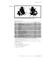
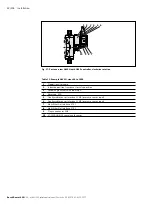
Page 52: ...xample A4VSO sizes 40 to 1000 1 Proportional solenoid 2 Inductive position transducer for valve position 3 Swivel angle actual value input X8A 4 Reserved X2N 5 Configurable sensor interface X2M2 pressure sensor input 6 Configurable sensor interface X2M1 pressure sensor input 7 Multi EtherNet interface X7E1 8 Multi EtherNet interface X7E2 9 Plug in connector XH4 10 VT SWA LIN G15 swivel angle senso...

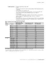
Page 53: ...reads MG max Required tightening torque of the threaded plugs MV WAF hexagon socket of the threaded plug Standard Thread size DIN 3852 M8 1 10 Nm 7 Nm1 3 mm M10 1 30 Nm 15 Nm2 5 mm M12 1 5 50 Nm 25 Nm2 6 mm M14 1 5 80 Nm 35 Nm1 6 mm M16 1 5 100 Nm 50 Nm1 8 mm M18 1 5 140 Nm 60 Nm1 8 mm M22 1 5 210 Nm 80 Nm1 10 mm M26 1 5 230 Nm 120 Nm1 12 mm M27 2 330 Nm 135 Nm1 12 mm M33 2 540 Nm 225 Nm1 17 mm M4...

Page 54: ...tings e g with a permanent marker 6 Check all pipes and hose lines and every combination of connecting pieces couplings or connecting points with hoses or pipes to ensure they are in condition for safe working 7 4 9 Electrically connecting the axial piston unit NOTICE Short circuit due to penetrating hydraulic fluid Fluid can penetrate the product and cause a short circuit Do not install axial pis...

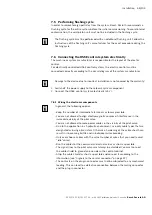
Page 55: ...Connect the HS5E control system electrically 24 V 7 6 1 Wiring the electronic components In general the following applies Keep the number of intermediate terminals as low as possible You are not allowed to align electromagnetic sources of interference in the immediate vicinity of the pilot valve You are not allowed to route power cables in the vicinity of the pilot valve Due to the application in ...

Page 56: ...n G15 swivel angle sensor which is directly connected to the HS5E pilot control valve ex works determines the pump s swivel angle The HS5E pilot control valve supplies the sensor 7 6 3 X2M1 and X2M2 Analog configurable pressure sensor interface coding A M12 5 pin socket Table 15 Pin assignment of X2M1 and X2M2 Pin Assignment 1 24 V voltage output sensor supply 1 2 Sensor signal input current 4 20 ...

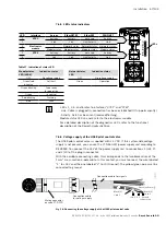
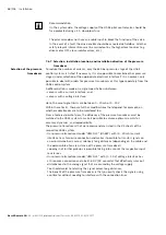
Page 57: ... to the two black wires of the 1 mm cross section 3 pole cable In this context you must connect the wire labeled 1 to 24 V and the one labeled 2 to L0 Ground The yellow green wire must be connected to ground Fig 18 Connecting the voltage supply of the HS5E pilot control valve Table 17 Indication of status LED Module status LED LED 4 Indication status Network status LED Indication status OFF No vol...

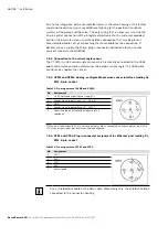
Page 58: ...al limits are between 0 20 mA or 0 10 V Within these limits there are further modifications that depend for example on whether cable breaks are to be monitored too From a technical point of view the efficiency of the pressure transducer must be matched to the HS5E system to make it possible to achieve optimum results for accuracy dynamics and reproducibility The pressure transducers that we recomm...

Page 59: ...tions right from the start If the installation position of the pump leads to a pressure transducer that is installed directly into the pump being positioned vertically we recommend choosing a different installation position for the pressure transducer The HM20 pressure transducer has a two wire current interface and it can be connected to the pilot valve via the central connector The supply voltag...

Page 60: ...functioning product with original accessories from Bosch Rexroth NOTICE Missing seals and plugs lead to noncompliance with the protection class Fluids and foreign particles can penetrate and damage the product Prior to commissioning make sure that all seals and connectors are tight Lack of hydraulic fluid Inadequate amounts of hydraulic fluid can destroy the product Make sure that the housing of t...

Page 61: ...the electronics are configured such that the system generates a warning message if the sensor system fails or malfunctions This warning message is not issued via an analog signal If required it is possible to change the configuration such that the system generates a fault message This message is output as an analog signal and it can be further processed Using the machine control unit you must ensu...

Page 62: ... fluids on delivery do not normally conform to the requirements for our components Use a suitable filter system to filter hydraulic fluids during filling to minimize solid impurities and water in the hydraulic system 2 Fill and air bleed the axial piston unit via the appropriate ports see chapter 7 3 Installation position on page 42 The hydraulic lines of the system must also be filled Notice Risk...

Page 63: ... the maximum pressure 5 Check the suction pressure at port S of the axial piston pump at nominal speed and maximum swivel angle Refer to data sheet 92050 for the permissible value 6 At maximum pressure check the leakage pressure at port K1 or K2 Refer to the data sheets in Table 1 Required and supplementary documentation on page 6 for the permissible value 8 1 3 Performing a functional test WARNIN...

Page 64: ...IP address is wrong the row is highlighted in red After you have configured the network port you can open IndraWorks and start a network search Fig 19 Connection selection By clicking on the OK pushbutton you can now establish a connection to the selected system If EtherCat or VARAN are activated as the fieldbus system you can deactivate them for direct communication with IndraWorks To do this cli...

Page 65: ...ts This mainly affects the following settings As delivered the command value specification is analog When using BUS you must make the corresponding master communication setting The settings for pressure acquisition with HS5E only not with HS5EP when using the supplied pressure transducer Setting of torque limitation For information on controller optimization see chapter 8 1 7 Setting controller pa...

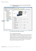
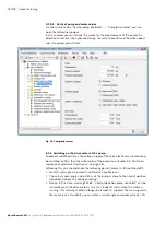
Page 66: ...een several pressure transducers The HS5E control system gives you the option of connecting two pressure transducers For this you must configure two assignments for the corresponding analog inputs with destination actual pressure value 1 P 0 2940 and actual pressure value 2 P 0 2941 The assignment with destination actual pressure value 1 must always be present since the HS5E control system always ...

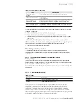
Page 67: ...o the torque of the pump at the actually set maximum displacement and to the value of pressure standardization or To protect the drive motor from overloading it is possible to limit the maximum torque of the pump Parameter P 0 2952 Torque limitation of pump relative is a relative variable in percent and is relative to the maximum torque of the pump at normal pressure P 0 2957 0 1 Determining the c...

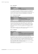
Page 68: ...ulic mechanical efficiency ηt Total efficiency ηt ηv ηhm Fig 22 Parameters for torque limitation At determination of the torque limitation value it is assumed that efficiencies are 100 Example Electric motor output of 75 kW at 1480 rpm should not be exceeded The pump of the NG 355 was limited mechanically to 320 cm3 The value for pressure standardization was input as 350 bar Electric motor T 60 00...

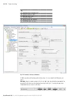
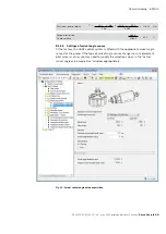
Page 69: ... 9 27 1 1782 5 8 1 5 4 Settings of swivel angle sensor At the factory the HS5E control system is fitted with the appropriate swivel angle sensor for the pump If the type of swivel angle sensor changers or a replacement pilot valve is set up you may need to modify the selection values in the Actual swivel angle value acquisition window appropriately Fig 23 Actual swivel angle value acquisition ...

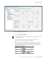
Page 70: ...ply of the valve electronics should always be switched on first then the drive motor of the pump see Chapter 5 9 Switch on sequence of electronics hydraulics on page 34 Following this you should check the following points motor is still switched off 1 No fault messages are present and the drive enable is set 2 The actual swivel angle value SWact of the pump is close to the neutral position swivele...

Page 71: ...t message disappears when the motor is switched on control difference now equal to zero Switch on the drive motor of the pump 8 1 7 Setting controller parameters The following description is to simplify setting of the controller parameters Depending on the application you may not need to modify all of the parameters listed here 8 1 7 1 Setting controller parameters for cascade structure Factory se...

Page 72: ... the pump system In the pressure controller there is a path for the integrator with feedback of the change in pressure This makes it possible to limit the integration value at transitions If the actual pressure value is in the range of the accuracy window by the pressure command value the integrator value is not adjusted any more 8 1 7 5 D component Table 22 D component Parameters Designation P 0 ...

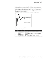
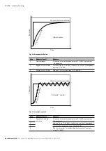
Page 73: ...is This means that it is generally enough to adapt the controller parameters in the pressure controller Below we will give you information about setting the individual parameters Fig 25 Damped oscillation Step Behavior result Measure 1 Overshoots damped oscillation Check the value of the dead volume P 0 2813 and correct it if necessary 2 Overshoots damped oscillation Increase feedback of integrato...

Page 74: ...still slow Reduce the integration time P 0 2806 0 4 Fig 27 Unstable control Step Behavior result Measure 1 Rapid but unstable response Check the value of the dead volume P 0 2813 and correct it if necessary 2 Reduce P gain P 0 2809 if necessary reduce D component 3 Increase the integration time P 0 2806 0 4 4 Reduce parameter for feedback derivation actual pressure value P 0 2812 Pressure Time Pre...

Page 75: ...s below in conjunction with a pressure sensor We recommend calibrating the HS5E control systemin the following order 1 Calibration of the pressure transducer provided by the customer 2 Calibration of the valve offset 3 Calibration of the swivel angle sensor s offset 4 Calibration of the swivel angle sensor s gain 5 Calibration of leakage compensation You can find further information about configur...

Page 76: ... controller calibration dialog Fig 29 Calibration For calibrating the HS5E control system the hydraulic fluid must have reached operating temperature 8 1 9 Saving parameters After carrying out commissioning you should save the parameter set of the HS5E pilot control valve If a malfunction occurs this is the only way to restore the parameters or transfer them to a replacement valve ...

Page 77: ...The volumetric and mechanical hydraulic efficiency increases as well through the conclusion of the running in phase of approx 10 operating hours To ensure that contamination in the hydraulic system does not damage the axial piston unit Bosch Rexroth recommends the following procedure after the running in phase After the running in phase have a hydraulic fluid sample analyzed for the required clean...

Page 78: ...equires no settings or changes during operation For this reason this chapter of the manual does not contain any information on adjustment options Use the product only within the performance range specified in the technical data The machine system manufacturer is responsible for the proper project planning of the hydraulic system and its control ...

Page 79: ...d electrical system of the axial piston unit Do not point the high pressure cleaner at sensitive components e g shaft seal ring electrical connections and electrical components For cleaning and care of the axial piston unit observe the following Check whether all seals and plug in connections are securely seated to ensure that no moisture can penetrate into the axial piston unit during cleaning Us...

Page 80: ...on the machine system and rectify them For this reason Bosch Rexroth recommends that the axial piston unit and system are always kept in a clean condition Daily Check axial piston unit for unusual noise development Daily Check fastening elements for tight seating All fasteners have to be checked when the hydraulic system is switched off depressurized and cooled down Monthly 10 3 Maintenance The ax...

Page 81: ...ble spare parts Spare parts which do not comply with the technical requirements as laid down by Bosch Rexroth can cause injury and property damage Use exclusively original spare parts from Rexroth to repair the Rexroth axial piston units otherwise the functional reliability of the axial piston unit cannot be assured and the warranty is void The spare parts lists for axial piston units are order sp...

Page 82: ...product to hard impacts and keep it away from magnetic parts Until it has been installed in the pump housing the original packaging is the safest place to store it Size ASSEMBLY KIT VT SWA LIN 1X G15 1 C20 R901425681 40 125 180 ASSEMBLY KIT VT SWA LIN 1X G15 2 C20 R901425682 71 ASSEMBLY KIT VT SWA LIN 1X G15 3 C20 R901425683 250 and larger Installing the VT SWA LIN G15 swivel angle sensor Tighten ...

Page 83: ...ntrol system on page 75 HS5E pilot control valve HS5E 6 CA 24L 2X VH Size 250 R901448624 HS5E pilot control valve HS5E 6 CA 40L 2X VH Size 250 R901448627 For HFC hydraulic fluids HS5E pilot control valve HS5E 6 CA 24L 2X MH Size 250 R901467728 HS5E pilot control valve HS5E 6 CA 40L 2X MH Size 250 R901467727 Undo the electrical connection on the pressure sensor s connector Replace the pressure tran...

Page 84: ...en the round connector after a short time This time is already taken into account in the defined tightening torque If used properly the IP 67 degree of protection is guaranteed without retightening One off retightening is possible However it is advisable not to retighten the plug in connection on a regular basis since this affects the electrical properties of the seal and its correct function ...

Page 85: ...to remove the axial piston unit 1 Make sure you have the appropriate tools and wear personal protective equipment 2 Check whether the hydraulic system is depressurized 3 Allow the axial piston unit to cool down until it can be removed without danger 4 For below reservoir installation before removing the axial piston unit from the complete system seal the connection to the reservoir or drain the re...

Page 86: ...al piston unit into its individual parts and properly recycle these parts 5 For example separate the parts into Castings Steel Aluminum Non ferrous metal Electronic waste Plastic Seals 13 Extension and conversion Do not modify the axial piston unit or its assembled parts This includes also the change of the setting screws or the wiring Changes to settings on the customer side should only be made u...

Page 87: ...general overview of how your product works in conjunction with the entire system Try to find out whether or not the product was working properly in conjunction with the entire system before the fault occurred Try to determine any changes to the entire system in which the product is installed Were there any changes to the product s application conditions or operating range Has maintenance work rece...

Page 88: ...sis At pin 3 of the central connector the signal drive ready can be output For this the factory assignment of the digital output to parameter P 0 0115 bit 1 must be activated This signal can be used to find out whether control is active and that no fault message is present Should a fault message occur during operation or the controller enable be withdrawn this bit is set to 0 Here the following ap...

Page 89: ...ic fluid Fill the suction line with hydraulic fluid Remove foreign particles from the suction line Drive speed too high Machine system manufacturer reduce drive speed Wrong direction of rotation Machine system manufacturer Check correct direction of rotation see Chapter 7 4 1 Preparation on page 44 Improper mounting of the axial piston unit Check the mounting of the axial piston unit according to ...

Page 90: ...ht too high suction pressure too low contaminants in the suction line impermissible filter in the suction line Machine system manufacturer Check the system e g optimize inlet conditions use suitable hydraulic fluid Fill the suction line with hydraulic fluid Remove foreign particles from the suction line Hydraulic fluid not in optimum viscosity range Machine system manufacturer check temperature ra...

Page 91: ...t Bosch Rexroth Service Malfunction of the control device or controller of the axial piston unit Contact Bosch Rexroth Service Control of the control device defective Check control contact machine system manufacturer or Bosch Rexroth Service Wear or mechanical damage to the axial piston unit Replace axial piston unit Contact Bosch Rexroth Service Output unit defective e g hydraulic motor or cylind...

Page 92: ...le sensor Internal electronics fault Have the pilot valve repaired by Rexroth Service or replace pilot valve Message Valve error pump controller deviation between command and actual position of the valve spool Valve spool jams due to contamination Replace pilot valve see chapter 10 5 1 on page 82 Internal electronics fault Replace pilot valve see chapter 10 5 1 on page 82 Message Control deviation...

Page 93: ...m Check mounting of the control system according to the specifications of the machine or system manufacturer Observe tightening torques Incorrect mounting of the assembled parts e g coupling and hydraulic lines Mount assembled parts according to the information provided by the coupling or fitting manufacturer Air in the pump or in the preload valve Bleed pump and preload valve Wear mechanical dama...

Page 94: ...on of actual pressure value acquisition Replace pressure transducer see page 58 Pressure transducer defective not connected Diagnosis Measure signal from PT and compare with indication on the pressure gauge Replace pressure transducer see page 58 Connect pressure transducer Pilot valve defective Replace pilot valve see chapter 10 5 1 on page 82 Insufficient flow Pressure controller active Increase...

Page 95: ...unction of the pressure control valves e g high pressure relief valve pressure cut off pressure controller Contact Rexroth Service Control system worn out Replace the control system contact Rexroth Service Setting of swivel angle sensor causes problems For more information on this topic refer to chapter 8 1 5 4 The connection to IndraWorks has failed the row on the display is red Input error Use 1...

Page 96: ...ual pressure value Input XH4 Pins 10 and 11 Analog voltage 0 to 10 V Analog current 0 to 20 mA With configuration to current input Maximum permissible input current 30 mA Ambient temperature range at the pump v 20 to 60 C Storage temperature range of pump electronics v 0 to 70 C 1 Supply voltage is used directly for sensor connections X2M1 X2M2 and X8M no internal voltage limitation 2 Outputs can ...

Page 97: ...24V Green 6 AO 2 Analog output 2 Factory setting Software actual value standardized OUT 10V or 0 20 mA Load I max 1 mA Violet 7 AI 1 Analog input 1 or digital input to be configured by means of software Factory setting Pressure command value standardized IN 10 V or 0 20 mA or 24 V digital Pink 8 AO 1 Analog output 1 Factory setting Actual pressure value standardized OUT 10V or 0 20 mA load I max 1...

Page 98: ...bility EMC EN 61000 6 2 EN 61000 6 3 EN 61000 4 2 ESD EN 61000 4 4 burst EN 61000 4 5 surge EN 61000 4 6 HF line conducted EN 55016 2 1 radio interference voltage 10 kV CD 15 kV AD with BWK B 2 kV with BWK B 0 5 kV sym asym with BWK B 10 Veff 150 kHz 80 MHz with BWK A 0 15 30 MHz Class A EN 55022 Maximum relative humidity non condensing 95 Design of electronics Integrated on pilot valve OBE Electr...

Page 99: ...C Cable sets 96 Calibration 75 Care 79 Central connector Pin assignment 96 Charge pump 23 Checking swivel angle measurement 95 Cleaning 79 Commissioning 60 initial 61 Connecting electrical 54 55 hydraulic 49 Connecting electrically 55 Controller parameter setting 71 Conversion 86 Corrosion protection 38 Corrosion protection film 38 D Designations 9 Dimensions 36 44 47 Direction of rotation 44 Disp...

Page 100: ...ions 44 on a gearbox 46 on gearbox 46 preparation 44 with cardan shaft 46 with coupling 45 with coupling 45 Installation conditions 40 Installation position above reservoir installation 43 below reservoir installation 42 Intended use 10 L Layout 23 Lifting device 36 Lifting strap 37 M Maintenance 79 80 Malfunction table 89 Master slave operation 30 switching off 32 switching over 32 Maximum workin...

Page 101: ... Port overview 51 Pressure transducer 58 mounting orientation 59 place of installation 59 replacing HM20 83 selection 58 Property damage 19 Pulsation damper 30 Q Qualification 11 R Recommissioning after standstill 77 Removal 85 performing 85 preparing 85 Repair 81 Replacement 85 pilot valve VT DFPD X 1X 82 pressure transducer HM20 83 seal kits 82 swivel angle sensor VT SWA LIN G15 82 Replacement o...

Page 102: ...e 38 Storing 38 Switching over to master slave operation 32 Switch on sequence 34 Swivel angle measurement check 95 Swivel angle sensor installation 82 Symbols 8 System requirements 33 T Technical data 96 Tightening torques 53 Tools 85 Transportation 36 with eye bolt 36 with lifting strap 37 Transporting 36 Transport protection 48 Troubleshooting 87 U Unit description 23 Unpacking 40 W Warranty 21...

Page 103: ...Alphabetical index 103 104 RE 92076 01 B 10 2017 A4 with HS5E pilot control valve Series 3x Bosch Rexroth AG ...

Page 104: ...n den Kelterwiesen 14 72160 Horb a N Germany Phone 49 7451 92 0 info ma boschrexroth de www boschrexroth com Subject to change Printed in Germany RE 92076 01 B 10 2017 Your local contact person can be found at www boschrexroth com addresses ...

Reviews: