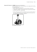
Installation 33/64
RE 92035-01-B/2019-11-25, A4VG Series 35, Bosch Rexroth AG
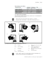
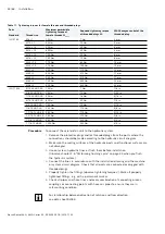
Table 8: Below-reservoir installation
Installation position
Air bleeding
the housing
Air bleeding the
stroking chamber
Filling
1 (drive shaft horizontal)
F
1
+
R
X
1
,
X
2
S
+ (
F
1
)
T
1
+
X
1
+
X
2
2 (drive shaft horizontal)
F
2
–
S
+ (
F
2
)
T
2
3 (drive shaft vertically down)
F
2
X
2
,
X
1
S
+ (
F
2
)
T
2
+
X
2
+
X
1
4 (drive shaft horizontal)
F
1
X
1
S
+ (
F
1
)
T
1
+
X
1
5 (drive shaft horizontal)
F
2
X
2
S
+ (
F
2
)
T
2
+
X
2
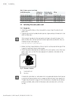
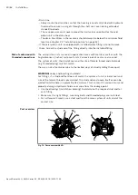
7.3.2 Above-reservoir installation
Above-reservoir installation means that the axial piston unit is installed above the
minimum fluid level of the reservoir.
Observe the maximum permissible suction height h
S max
= 800 mm.
The permissible suction height h
S
is derived from the total pressure loss.
6
7
8
9
10
h
t min
h
min
SB
h
S max
F
1
X
1
,
X
2
S
R
F
2
T
1
F
2
F
1
T
2
S
h
S max
SB
h
t min
h
min
h
t min
h
min
X
2
,
X
1
h
S max
F
2
SB
F
1
T
2
S
F
1
T
1
S
X
1
h
t min
h
min
h
S max
SB
X
2
F
2
h
t min
h
min
h
S max
SB
F
2
F
1
S
X
2
T
2
X
1
R
R
Fig. 10: Above-reservoir installation A4VG with installation positions 6–10
T
1
,
T
2
Drain port
h
t min
Minimum required immersion depth
(200 mm)
F
1
,
F
2
Filling/air bleeding
h
min
Minimum required distance to
reservoir bottom (100 mm)
R
Air bleed port
h
S max
Maximum permissible suction height
(800 mm)
S
Suction port
SB
Baffle (baffle plate)
X
1
,
X
2
Control pressure port
Ports
F
1
and
F
2
are part of the external piping and must be provided on the
customer side to make filling and air bleeding easier.

