Installation 35/68
RE 92004-01-B/05.2017, A4VG Series 40,
Bosch Rexroth AG
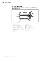
The direction of rotation as specified on the name plate determines the direction of
rotation of the axial piston unit as viewed on the drive shaft, see chapter 5.4 “Product
identification” on page 24. For information on the direction of rotation of the
drive motor, please refer to the drive motor manufacturer's instruction manual.
7.4.2 Dimensions
The installation drawing contains the dimensions for all connections and ports on
the axial piston unit. Also observe the manuals provided by the manufacturers of
the other hydraulic components when selecting the required tools.
7.4.3 General instructions
Follow these general instructions when installing the axial piston unit:
• Note that you can expect certain installation positions to affect the control device.
Gravity, dead weight and case pressure can cause minor characteristic shifts and
changes in response time.
• Torsional vibrations and speed variations may cause leakages on the shaft seal and
increased rotary angular accelerations of the rotary group of the axial piston unit.
At risk are diesel drives with a small number of cylinders and low flywheel mass
and toothed belt or V-belt drives. Belts can lose a large part of their pre-charge
pressure after just a short operating time.
An automatic clamping device can lessen the speed variations and vibrations and
thus avoid subsequential damage.
– When using toothed belts or v-belts to transfer the input or output drive, always
use an automatic clamping device.
• On the input or output drive of an axial piston unit, a cardan shaft may cause
vibrations and impermissible rotary angle accelerations. Depending on the
frequency and temperature, they may cause leakages on the shaft seal and damage
to the rotary group.
• If a shared drain line is used for several units, make sure that the respective case
pressure is not exceeded. The shared drain line must be dimensioned to ensure
that the maximum permissible case pressure of all connected units is not exceeded
in any operational conditions, particularly at cold start. If this is not possible,
separate drain lines must be laid, if necessary.
The type of installation to be used for the axial piston unit depends on the connecting
elements to the drive side. The following descriptions explain the installation of the
axial piston unit:
• with a coupling
• on a gearbox
• to a cardan shaft

