Installation 39/68
RE 92004-01-B/05.2017, A4VG Series 40,
Bosch Rexroth AG
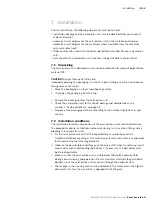
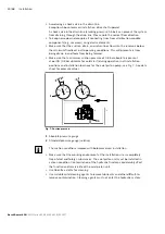
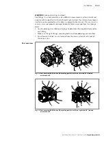
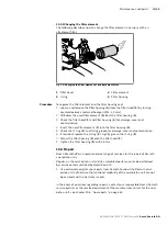
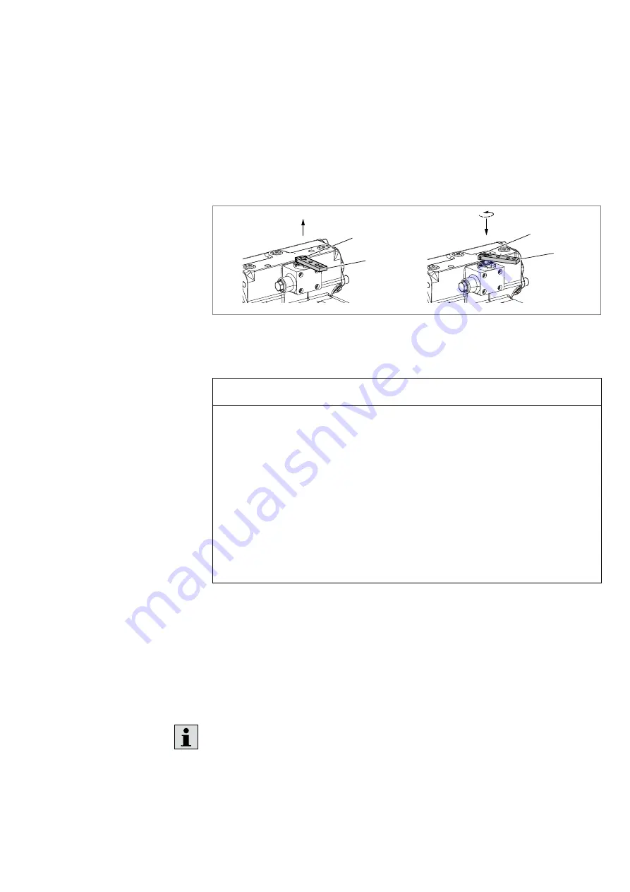
7.4.8 Changing the lever position of the Hw control
If necessary, you can change the position of the lever by turning.
• Hexagon socket wrench with WAF 10 mm
1.
Loosen and remove the mounting bolt (
1
) of the HW lever (
2
).
2.
Pull the HW lever up, turn it into the desired position and push it back down.
3.
Tighten the mounting bolt (
1
) again.
Tightening torque
M
A
= 6.5 Nm.
1
2
1
2
Fig. 12: Changing the lever position of the Hw control
7.4.9 Hydraulically connecting the axial piston unit
NOTICE
Insufficient suction pressure!
Generally, a minimum permissible suction pressure at port
S
is specified for axial
piston pumps in all installation positions. If the pressure at port
S
drops below the
specified values, damage may occur which may lead to the axial piston pump being
damaged beyond repair!
▶
Make sure that the necessary suction pressure is not undercut. This is
influenced by:
– the piping (e.g. suction cross-section, pipe diameter, length of suction line)
– The position of the reservoir
– The viscosity of the hydraulic fluid
– A filter element or check valve in the suction line, if these are fitted (regularly
check the filter element’s level of contamination)
The machine/system manufacturer is responsible for dimensioning the lines. The
axial piston unit must be connected to the rest of the hydraulic system in accordance
with the hydraulic circuit diagram of the machine/system manufacturer.
The ports and fastening threads are designed for the maximum permissible
pressures
p
max
, see Table 10 “Ports A4VG Series 40Series 40” on page 42. The
machine/system manufacturer must ensure that the connecting elements and lines
correspond to the specified application conditions (pressure, flow, hydraulic fluid,
temperature) with the necessary safety factors.
Connect only hydraulic lines that are appropriate for the axial piston unit port
(pressure level, size, system of units).
Required tools
Procedure

