background image

46/68 Commissioning

Bosch Rexroth AG

, A4VG Series 40, RE 92004-01-B/05.2017

8  Commissioning

 wARnInG

Danger while working in the danger zone of a machine/system!

Danger to life or risk of injury or serious injury!


Pay attention to and eliminate potential danger sources before operating  
the axial piston unit.


Make sure no one is in the danger zone of the machine/system.


The emergency stop button for the machine/system must be within the 
operator’s reach.


Always follow the instructions of the machine/system manufacturer during 
commissioning.

 CAUTIOn

Commissioning an improperly installed product!

Risk of injury and property damage!


Make sure that all electrical and hydraulic ports are connected or plugged.


Only commission a completely installed, fully functioning product with original 
accessories from Bosch Rexroth.

8.1  Initial commissioning

During all work for commissioning the axial piston unit, observe the general 
safety instructions and intended use detailed in chapter 2 “Safety instructions” 
on page 9. 


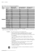
Connect the pressure gauge for the boost pressure, working pressure, case 
pressure and suction pressure to the specified measuring points on the axial 
piston unit or in the hydraulic system, to check the technical data at first 
operation.


During the commissioning process, monitor the temperature of the hydraulic fluid 
in the reservoir to ensure that it lies within the permissible viscosity limits.

Summary of Contents for Rexroth A4VG 40 Series

Page 1: ...Instruction manual RE 92004 01 B 05 2017 Replaces 04 2008 English Axial piston variable pump A4VG Series 40 ...

Page 2: ...concerning a certain condition or suitability for a certain application can be derived from our information The information given does not release the user from the obligation of own judgment and verification It must be remembered that our products are subject to a natural process of wear and aging The cover shows an example application The product delivered may differ from the image on the cover ...

Page 3: ...nce description 20 5 2 Product description 20 5 2 1 Layout of the axial piston unit 20 5 2 2 Functional description 21 5 3 Bypass function 22 5 3 1 Activating and deactivating the bypass function 23 5 4 Product identification 24 6 Transport and storage 25 6 1 Transporting the axial piston unit 25 6 1 1 Transporting by hand 25 6 1 2 Transporting with a lifting device 25 6 2 Storing the axial piston...

Page 4: ...functional test 48 8 2 Running in phase 49 8 3 Recommissioning after a standstill 49 9 Operation 50 10 Maintenance and repair 51 10 1 Cleaning and care 51 10 2 Inspection 52 10 3 Maintenance 52 10 3 1Changing the filter element 53 10 4 Repair 53 10 5 Spare parts 54 11 Removal and replacement 55 11 1 Required tools 55 11 2 Preparing for removal 55 11 3 Performing removal 55 11 4 Preparing the compo...

Page 5: ...tion drawing Axial piston variable pump A4VG Series 40 Contains the permissible technical data 92004 Data sheet Mineral oil based hydraulic fluids and related hydrocarbons Describes the requirements on a mineral oil based hydraulic fluid and related hydrocarbons for operation with Rexroth hydraulic components and assists you in selecting a hydraulic fluid for your hydraulic system 90220 Data sheet...

Page 6: ...nd in chapter 3 General instructions on damage to property and the product on page 16 and before a sequence of actions or an instruction for action involving a risk of personal injury or damage to equipment The described danger prevention measures must be observed Safety instructions are set out as follows Signal word Type and source of danger Consequences of noncompliance Measures to prevent dang...

Page 7: ...g symbols indicate information that is not safety relevant but increases understanding of the documentation Table 3 Meaning of the symbols Symbol Meaning If this information is disregarded the product cannot be used and or operated to the optimum extent Single independent action 1 2 3 Numbered instruction The numbers indicate that the actions must be completed one after the other 1 3 3 Designation...

Page 8: ...ric ET Electric control direct operated with two pressure reducing valves DRE EV Electric control direct operated EZ Two point control electric HP Proportional control hydraulic pilot pressure related HW Proportional control hydraulic mechanical servo HT Hydraulic control direct operated ISO International Organization for Standardization JIS Japan Industrial Standard RE Rexroth document in the Eng...

Page 9: ...n established in accordance with the Machinery Directive This product is intended for the following use The axial piston unit is only approved as a pump for hydrostatic drives in closed circuit Observe the technical data the application and operating conditions and the performance limits as specified in data sheet 92004 and in the order confirmation Information about approved hydraulic fluids can ...

Page 10: ...in this documentation require basic mechanical electrical and hydraulics expertise as well as knowledge of the associated technical terms For transporting and handling the product additional knowledge is necessary with regard to working with lifting devices and their slings In order to ensure safe use these activities should only be performed by skilled personnel or an instructed person under the ...

Page 11: ...mitted in the product documentation for example in explosion protection applications or in safety related parts of a control system functional safety You may only commission the product if it has been determined that the end product for example machinery or system in which the Rexroth products are installed complies with the country specific provisions safety regulations and standards for the appl...

Page 12: ... bones or damage to the product Make sure that the load bearing capacity of the lifting device is sufficient to safely bear the weight of the axial piston unit Never stand or put your hands under a suspended load Make sure the unit remains stable during transport Wear your personal protective equipment e g safety goggles safety gloves suitable working clothes safety shoes Use suitable lifting devi...

Page 13: ...ted machine movements Use the manual override only for functional testing or in the event of technical malfunctions Using the manual override on a permanent basis e g by wedging blocking is not permitted The use of the manual override is only permitted with limited technical data e g 0 25 maximum data Check whether additional protective measures are necessary for the application on your machine in...

Page 14: ...ion when in the vicinity of the operating axial piston unit Hot surfaces on the axial piston unit Risk of burning Allow the axial piston unit to cool down sufficiently before touching it Wear heat resistant protective clothing e g gloves Improper routing of cables and lines Risk of stumbling and property damage Improper routing of cables and lines can cause a risk of stumbling as well as damage to...

Page 15: ...eal the leak or hydraulic fluid jet with a cloth Danger from improper handling Risk of slipping Risk of slipping on wet surfaces when climbing on the axial piston unit Never grab or climb onto the axial piston unit Check how to safely get on top of the machine system 2 7 Personal protective equipment Personal protective equipment is the responsibility of the user of the axial piston unit Observe t...

Page 16: ...destroyed Never operate the axial piston unit with insufficient hydraulic fluid Specifically make sure that the rotary group has sufficient lubrication When commissioning a machine system make sure that the housing area and the working lines of the axial piston unit are filled with hydraulic fluid and remain filled during operation Air inclusions in the forward drive shaft bearing are to be preven...

Page 17: ...e solid particle contamination and water in the hydraulic system Improper cleaning Product can get damaged Plug all openings with the appropriate protection equipment in order to prevent cleaning agents from entering the hydraulic system Never use solvents or corrosive cleaning agents Use only water and if necessary a mild cleaning agent to clean the axial piston unit Do not point a high pressure ...

Page 18: ...he safety data sheet for the hydraulic fluid and the specifications provided by the system manufacturer Danger from hot components Nearby products can become damaged Components which heat up e g solenoids can cause damage to nearby products if they are too close during installation When installing the axial piston unit check the distances to nearby products to ensure that they do not get damaged T...

Page 19: ...3 2 Fig 1 Axial piston unit The scope of delivery includes the following Axial piston unit as per order confirmation The following parts are also assembled prior to delivery Protective covers 1 Protective plug threaded plug 2 For version with through drive metallic protective cover and mounting bolts 3 ...

Page 20: ...isplacement The flow can be changed steplessly by controlling the swashplate cradle 13 For axial piston units with swashplate design the pistons are arranged axially relative to the drive shaft In the closed circuit the hydraulic fluid flows from the hydraulic pump to the consumer e g hydraulic motor and from there directly back to the hydraulic pump There is a high pressure side and a low pressur...

Page 21: ...e relief valves protect the hydrostatic transmission pump and motor from overloading They limit the maximum pressure in the respective high pressure line and serve simultaneously as boost valves High pressure relief valves are not working valves and are only suitable for pressure peaks or high rates of pressure change The boost pump 7 continuously supplies a sufficient volume of fluid boost volume...

Page 22: ...g the swivel angle changes the piston stroke and therefore the displacement Controlling the swashplate through the neutral position will change the direction of flow making reversing operation possible The swivel angle is controlled hydraulically by the stroking piston 3 The cradle is mounted in swivel bearings for easy motion and the neutral position is spring centered Increasing the swivel angle...

Page 23: ...istances result in impermissible heat generation and inadequate lubrication This overheats and damages the axial piston unit Wear heat resistant protective clothing for example gloves Only tow the vehicle out of the immediate danger zone Notice Draining the hydraulic circuit Risk of damage While towing with the bypass function activated the closed hydraulic circuit drains itself This can result in...

Page 24: ...Elchingen Made in Germany A4VG110EP2D0000 40MRND6T21F0000AS00 0 R90XXXXXXX SC X 12345678 17W02 n XXXX min 1 P XXX kW m XXX kg 7202 Fig 4 Name plate A4VG 1 Manufacturer 2 Internal plant designation 3 Sample category optional 4 Direction of rotation viewed on drive shaft here clockwise 5 Specified area for inspection stamp 6 Weight optional 7 Power 8 Bar code 9 Rotational speed 10 Manufacturing date...

Page 25: ...ly for a short time if necessary Caution Danger from heavy loads Health hazard from carrying axial piston units Use suitable lifting lowering and moving methods Wear your personal protective equipment e g safety goggles safety gloves suitable working clothes safety shoes Do not use sensitive assembled parts to transport the axial piston unit e g sensors or valves Carefully place the axial piston u...

Page 26: ...nd cause injuries Use the widest possible lifting strap Make sure that the axial piston unit is securely fixed with the lifting strap Only guide the axial piston unit by hand for fine positioning and to avoid oscillations Never stand or put your hands under a suspended load Place the lifting strap around the axial piston unit in such a way that it does not pass over assembled parts e g valves pipi...

Page 27: ...orage times for an originally packed axial piston unit as per data sheet 90312 Table 7 Storage time with factory corrosion protection Storage conditions Standard corrosion protection Long term corrosion protection optional Closed dry room at an even temperature between 5 C and 20 C Undamaged and sealed corrosion protection film Maximum 12 months Maximum 24 months Warranty is void if the requiremen...

Page 28: ...0 1 Cleaning and care on page 51 2 Empty the axial piston unit 3 For storage times up to 12 months Coat the inside of the axial piston unit with mineral oil and fill with about 100 ml mineral oil For storage times up to 24 months Fill the axial piston unit with corrosion protection VCI 329 20 ml Filling is done through the drain port T1 or T2 see chapter 7 4 Installing the axial piston unit Fig 13...

Page 29: ...nit Check the axial piston unit for transport damage and completeness see chapter 4 Scope of delivery on page 19 Dispose of the packaging material according to the national regulations in your country 7 2 Installation conditions The installation location and position of the axial piston unit essentially determine the procedures during installation and commissioning such as when filling and air ble...

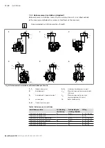
Page 30: ...on pressure of 0 8 bar absolute is present at port S 0 5 bar absolute for cold start during operation in all installation positions and installation locations for the axial piston pump see Fig 7 See data sheet for pressure values 0 2 0 8 abs 1 2 3 0 0 1 2 1 2 1 S Fig 7 Suction pressure 1 Absolute pressure gauge 2 Standard pressure gauge relative The suction conditions improve with below reservoir ...

Page 31: ...e final installation position then the filling must be effected before installation e g in installation position 2 To prevent unexpected actuation and damage the stroking chambers must be air bled via the ports X1 X2 or X3 X4 depending on the installation position For installation position 4 and 10 drive shaft upwards you need the additional air bleed port R1 in the flange area This port is not pr...

Page 32: ...voir installation with installation position 1 6 T1 T2 Highest drain port X3 X4 Stroking chamber pressure port R Air bleed port ht min Minimum required immersion depth 200 mm R1 Air bleed port special version hmin Minimum required distance to reservoir bottom 100 mm S Suction port SB Baffle baffle plate X1 X2 Control pressure port Table 8 Below reservoir installation Installation position Air blee...

Page 33: ...t min hmin hS max T2 S F2 SB F1 X2 X1 ht min hmin hS max T1 S F2 SB 0 5 bar F1 R1 X4 X3 ht min hmin hS max X3 T2 T1 S F2 SB F1 X1 X2 X1 X2 ht min hmin hS max X4 T2 T1 S SB F2 F1 ht min hmin T1 F2 S R SB hS max F1 X2 X1 Fig 9 Above reservoir installation A4VG with installation position 7 12 T1 T2 Highest drain port X3 X4 Stroking chamber pressure port F1 F2 Filling air bleeding ht min Minimum requi...

Page 34: ... the specifications on the name plate of the axial piston unit to see if the axial piston unit is correct 2 Compare the material number and designation type code with the details in the order confirmation If the material number for the axial piston unit does not correspond to the one in the order confirmation contact your local contact person for clarification you can find the address under www bo...

Page 35: ... unit At risk are diesel drives with a small number of cylinders and low flywheel mass and toothed belt or V belt drives Belts can lose a large part of their pre charge pressure after just a short operating time An automatic clamping device can lessen the speed variations and vibrations and thus avoid subsequential damage When using toothed belts or v belts to transfer the input or output drive al...

Page 36: ...corrosion and the associated wear 3 Transport the axial piston unit to the installation location 4 Remove dirt and foreign particles from the installation location 5 Install the coupling on the output shaft of the drive motor in accordance with the specifications provided by the coupling manufacturer The axial piston unit must not be tightened down until the coupling has been correctly installed 6...

Page 37: ...it and leaks at the shaft seal Improperly installed cardan shafts generate unbalances This results in vibrations and impermissible forces on the drive shaft Observe the cardan shaft manufacturer s assembly instructions 1 Position the axial piston unit close to the specified installation location Allow enough space for the cardan shaft to fit through on both sides 2 Position the cardan shaft on the...

Page 38: ... metallic protective cover and mounting bolts Ports intended for connecting lines are provided with protective plugs or threaded plugs which serve as transport protection All ports required for functional operation must be connected see Table 10 Ports A4VG Series 40Series 40 on page 42 Failure to do so could lead to malfunctions or damage If a port is not connected it must be plugged with a thread...

Page 39: ...e necessary suction pressure is not undercut This is influenced by the piping e g suction cross section pipe diameter length of suction line The position of the reservoir The viscosity of the hydraulic fluid A filter element or check valve in the suction line if these are fitted regularly check the filter element s level of contamination The machine system manufacturer is responsible for dimension...

Page 40: ...e range specified in data sheet 92004 see Table 10 Drain line Always route the drain lines so that the housing is constantly filled with hydraulic fluid and to ensure that no air gets through the shaft seal even during extended standstill periods Under no operating circumstances may the case pressure exceed the maximum limit values specified for the axial piston unit in the data sheet The drain li...

Page 41: ...luid can escape from this leakage point Use the drawings installation drawing to determine the required stud end for each fitting Make sure the right fittings mounting bolts and threaded plugs are installed For all female threads use a stud end from the same system of units and of the correct size T1 G PS X1 R X2 X4 YST S A B T2 X3 X1 R X2 MH MA MB Fig 13 Port overview A4VG Series 40 working ports...

Page 42: ...X YST Pilot pressure port outlet DA 6 only 40 O YHT Pilot pressure port outlet HT only 40 O MA MB Measuring port pressure A B 500 X MH Measuring port high pressure 500 X Y1 Y2 Pilot pressure port pilot signal HD only 40 O Z Pilot pressure port inch signal DA 5 only 80 O 1 The measuring system and thread size can be taken from the installation drawing 2 Short term pressure peaks may occur depending...

Page 43: ... torques MG max are maximum values of the female threads and must not be exceeded For values see Table 11 Threaded plugs For the metallic threaded plugs supplied with the axial piston unit the required tightening torques of threaded plugs MV apply For values see Table 11 Mounting bolts For mounting bolts with metric ISO thread according to DIN 13 or thread according to ASME B1 1 we recommend check...

Page 44: ... valid for the condition dry and lightly oiled 2 The tightening torques for the threaded plugs are valid for the condition dry in the condition lightly oiled the tightening torques for M10 1 are reduced to 10 Nm and for M12 1 5 to 17 Nm To connect the axial piston unit to the hydraulic system 1 Remove the protective plugs or threaded plugs at the ports at which the connections are to be made accor...

Page 45: ... data sheet 92004 The mating connector is not included in the scope of delivery 1 Switch off the power supply to the relevant system component 2 Electrically connect the axial piston unit 12 or 24 V Before connecting check that the connector including all seals is intact If necessary you can change the position of the connector by turning the solenoid body This is not dependent on the connector ve...

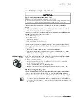
Page 46: ...f injury and property damage Make sure that all electrical and hydraulic ports are connected or plugged Only commission a completely installed fully functioning product with original accessories from Bosch Rexroth 8 1 Initial commissioning During all work for commissioning the axial piston unit observe the general safety instructions and intended use detailed in chapter 2 Safety instructions on pa...

Page 47: ...draulic fluid The cleanliness levels of hydraulic fluids on delivery do not normally conform to the requirements for our components Use a suitable filter system to filter hydraulic fluids during filling to minimize solid impurities and water in the hydraulic system 2 Fill and air bleed the axial piston unit via the appropriate ports see chapter 7 3 Instal lation position on page 31 The hydraulic l...

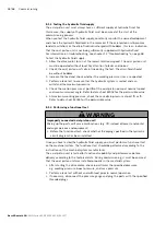
Page 48: ...and the maximum pressure 5 Check the suction pressure at port S of the axial piston pump at nominal speed and maximum swivel angle Refer to data sheet 92004 for the permissible value 6 At maximum working pressure check the case drain pressure at port T1 or T2 Refer to data sheet 92004 for the permissible value 8 1 3 Performing a functional test WARNING Improperly connected axial piston unit Mixing...

Page 49: ...ric and mechanical hydraulic efficiency increases as well until the conclusion of the running in phase of approx 10 operating hours To ensure that contamination in the hydraulic system does not damage the axial piston unit Bosch Rexroth recommends the following procedure after the running in phase After the running in phase have a hydraulic fluid sample analyzed for the required cleanliness level ...

Page 50: ...tings or changes during operation For this reason this chapter of the manual does not contain any information on adjustment options Use the product only within the performance range specified in the technical data The machine system manufacturer is responsible for the proper project planning of the hydraulic system and its control ...

Page 51: ...l system of the axial piston unit Do not point the high pressure cleaner on sensitive components for example shaft seal electrical connections and components For cleaning and care of the axial piston unit observe the following Check whether all seals and plug in connections are securely seated to ensure that no moisture can penetrate into the axial piston unit during cleaning Use only water and if...

Page 52: ...ght seating All fasteners have to be checked when the hydraulic system is switched off depressurized and cooled down Monthly Change the filter element in optionally mounted filters The replacement interval may vary depending on the degree of contamination of the hydraulic fluid We recommend using a contamination indicator Half yearly or every 500 operating hours whichever occurs first 10 3 Mainten...

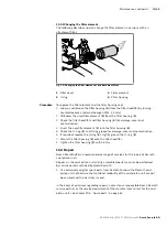
Page 53: ...ter housing 4 5 Check the O ring 2 and O ring groove for damage wear and contamination 6 If required replace the O ring 2 Lightly grease the O ring 2 7 Screw the filter housing 4 onto the filter head 1 8 Tighten the filter housing 4 with 45 Nm 10 4 Repair Bosch Rexroth offers a comprehensive range of services for the repair of Rexroth axial piston units Repairs on the axial piston unit and its ass...

Page 54: ...are parts lists for axial piston units are order specific When ordering spare parts quote the material and serial number of the axial piston unit as well as the material numbers of the spare parts Address all questions regarding spare parts to your responsible Bosch Rexroth Service partner or the service department of the manufacturer s plant for the axial piston unit Bosch Rexroth AG Glockeraustr...

Page 55: ... as follows to remove the axial piston unit 1 Make sure you have the appropriate tools and wear personal protective equipment 2 Allow the axial piston unit to cool down until it can be removed without danger 3 For below reservoir installation before removing the axial piston unit from the complete system seal the connection to the reservoir or drain the reservoir 4 Place a drip tray under the axia...

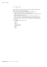
Page 56: ...iston unit of hydraulic fluid 2 Dispose of the axial piston unit and packaging material in accordance with the national regulations in your country 3 Dispose of the hydraulic fluid according to the national regulations in your country Also observe the applicable safety data sheet for the hydraulic fluid 4 Disassemble the axial piston unit into its individual parts and properly recycle these parts ...

Page 57: ...ecific setting instructions The warranty from Bosch Rexroth only applies to the product configuration as delivered The warranty is void if the unit is modified or extended Setting screws are protected against unauthorized resetting by means of tamper proof caps Removal of the tamper proof caps will void the warranty If you need to change the settings please contact your local contact person you ca...

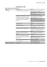
Page 58: ...w of how your product works in conjunction with the entire system Try to find out whether or not the product was working properly in conjunction with the entire system before the fault occurred Try to determine any changes to the entire system in which the product is installed Were there any changes to the product s application conditions or operating range Has maintenance work recently been carri...

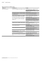
Page 59: ...e filter as necessary Drive speed too high Machine system manufacturer reduce drive speed Wrong direction of rotation Machine system manufacturer check correct direction of rotation see chapter 7 4 1 Prepara tion on page 34 Improper mounting of the axial piston unit Check the mounting of the axial piston unit according to the specifications of the machine system manufacturer observe tightening tor...

Page 60: ...r too small or blocked etc Machine system manufacturer Check the system e g optimize inlet conditions use suitable hydraulic fluid Fill the suction line with hydraulic fluid Remove foreign particles from the suction line Check the filter system and change the filter as necessary Hydraulic fluid not in optimum viscosity range Machine system manufacturer check temperature range and use suitable hydr...

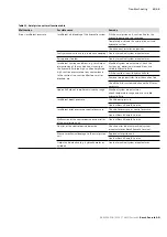
Page 61: ...c Machine system manufacturer Check the system e g optimize inlet conditions use suitable hydraulic fluid Fill the suction line with hydraulic fluid Remove foreign particles from the suction line Check the filter system and change the filter as necessary Hydraulic fluid not in optimum viscosity range Machine system manufacturer check temperature range and use suitable hydraulic fluid Insufficient ...

Page 62: ...ssure limitation and pressure control valves of the axial piston unit boost pressure relief valve high pressure relief valve pressure cut off Air bleed the axial piston unit and hydraulic system Contact Bosch Rexroth Service Unstable control signal Contact machine system manufacturer or Bosch Rexroth Service Malfunction in the control devices or the controller Contact Bosch Rexroth Service Excessi...

Page 63: ...xial piston unit can be found in the data sheet 92004 The data sheet can be found on the Internet at www boschrexroth com mediadirectory Additional information can be found in the online product catalog Mobile Hydraulics www boschrexroth com axial piston pumps Order related technical data for your axial piston unit can be found in the order confirmation ...

Page 64: ...Bosch Rexroth AG A4VG Series 40 RE 92004 01 B 05 2017 64 68 ...

Page 65: ...RE 92004 01 B 05 2017 A4VG Series 40 Bosch Rexroth AG 65 68 ...

Page 66: ... 25 F Filling 47 Filter 52 53 Changing 53 Flushing cycle 45 Functional description Control 22 Functional test 48 I Identification 24 Inspection 52 Installation 29 34 Completing 37 general instructions 35 On a gearbox 37 On gearbox 37 Preparation 34 With coupling 36 Installation conditions 29 Installation position Above reservoir installation 33 Below reservoir installation 32 Intended use 9 L Layo...

Page 67: ...49 S Safety instructions 9 General 11 Product specific 12 Signal word 6 Scope of delivery 19 Slipper pad 20 Solenoid position Changing 45 Spare parts 54 Storage 25 Storage time 27 Storing 27 Stroking piston 20 Symbols 7 T Technical data 63 Tightening torques 43 Tools 55 Transportation 25 by hand 25 with eye bolt 25 with lifting strap 26 Transporting 25 Transport protection 38 Troubleshooting 58 U ...

Page 68: ... Glockeraustraße 4 89275 Elchingen Germany Phone 49 7308 82 0 info ma boschrexroth de www boschrexroth com Subject to change Printed in Germany RE 92004 01 B 05 2017 Your local contact person can be found at www boschrexroth com addresses ...

Reviews: