background image

Bosch Rexroth AG

, RE 92202/02.2015

38

A7VO Series 63 

| Axial piston variable pump

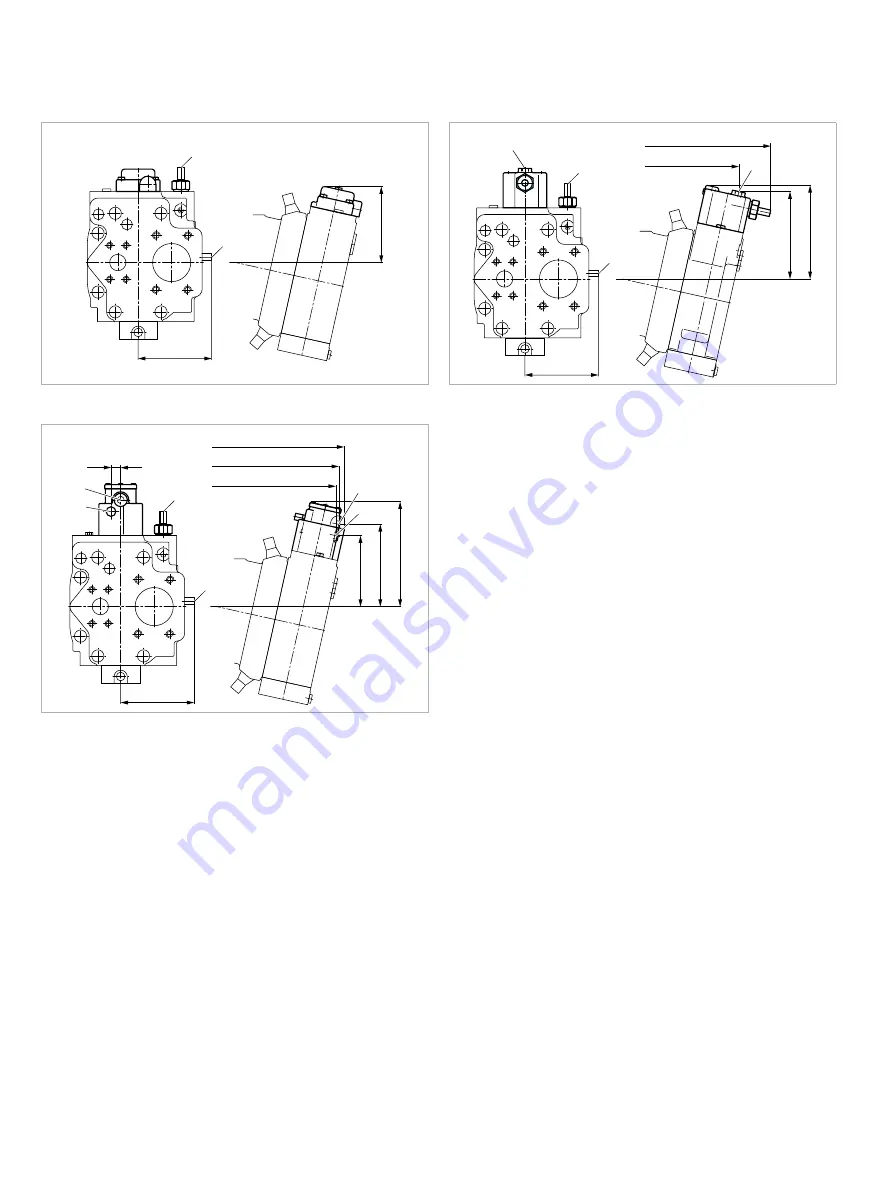
Dimensions, size 160

Dimensions [mm]


▼ LRD 

– Power controller with pressure cut-off


▼ LRDS 

– Power control with pressure cut-off and load sensing

D

LR

150

145

X

4

X

4

329 (X

4

)

392

D

LR

185

172

145


▼ LRDH1 

– Power control with pressure cut-off and stroke limiter

Y

3

X

1

Y

3

X

1

D

LR

19

162

207

140

340 (X

1

)

334 (Y

3

)

145

351


Summary of Contents for Rexroth A7VO 63 Series

Page 1: ...ure 400 bar Open circuit Axial piston variable pump A7VO Series 63 RE 92202 Edition 02 2015 Replaces 05 2012 Ordering code 2 Hydraulic fluids 4 Shaft seal ring 5 Flow direction 5 Operating pressure range 6 Technical data 7 LR Power controller without power override 9 LA1 Power controller with hydraulically proportional power override 13 DR Pressure controller 15 HD Proportional hydraulic control 1...

Page 2: ...verride only available for clockwise rotation and with port plate 02 with load sensing LA1S with load sensing and hydraulically proportional LS override LA1S5 Pressure controller DR remotely controlled DRG with load sensing DRS Proportional control hydraulic Positive control Δp 10 bar HD1 with pressure cut off remotely controlled Positive control Δp 10 bar HD1G Proportional control electrical Posi...

Page 3: ...oids1 see page 40 11 Without connector without solenoid with hydraulic control only without code DEUTSCH molded connector 2 pin without suppressor diode P Standard special version 12 Standard version without code Special version S Available Not available Preferred program Notes Note the project planning notes on page 42 Preservation Up to 12 months as standard Up to 24 months long term state in pl...

Page 4: ...ns above due to extreme operating parameters we recommend flushing the case at port U Viscosity and temperature of hydraulic fluids Viscosity Temperature Comment Cold start νmax 1600 mm2 s θSt 40 C t 3 min n 1000 rpm without load p 50 bar Permissible temperature difference ΔT 25 K between axial piston unit and hydraulic fluid in the system Warm up phase ν 1600 to 400 mm2 s θ 40 C to 25 C at p 0 7 ...

Page 5: ...roller or pressure cut off a drain line is needed to relieve port T1 to the reservoir Shaft seal ring Permissible pressure loading The service life of the shaft seal is influenced by the speed of the axial piston unit and the leakage pressure in the housing case pressure Momentary pressure spikes t 0 1 s up to 10 bar are allowed The service life of the shaft seal decreases with increasing frequenc...

Page 6: ...e to the axial piston unit Rate of pressure change RA max 16000 bar s Maximum permissible rate of pressure build up and reduction during a pressure change over the entire pressure range Pressure at suction port S Inlet Minimum pressure pS min 0 8 bar absolute Minimum pressure at suction port S inlet that is required to avoid damage to the axial piston unit The minimum required pressure is dependen...

Page 7: ...1 7 1 5 1 3 1 5 1 4 1 3 1 2 1 1 1 0 0 9 0 8 Displacement Vg Vg max Speed n n nom Inlet pressure p abs Determining operating characteristics Flow qv Vg n ηv l min 1000 Torque T Vg Δp Nm 20 π ηmh Power P 2 π T n qv Δp kW 60000 600 ηt Key Vg Displacement per revolution cm3 Δp Differential pressure bar n Rotational speed rpm ηv Volumetric efficiency ηmh Mechanical hydraulic efficiency ηt Total efficie...

Page 8: ...5 500 710 900 11250 Permissible axial force per bar operating pressure Fax perm bar N bar 4 6 7 5 9 6 11 3 15 1 Effect of radialforce Fq on the service life of bearings By selecting a suitable direction of radial force Fq the load on the bearings caused by the internal rotary group forces can be reduced thus optimizing the service life of the bearings Recommended position of mating gear is depen d...

Page 9: ...ce the control valve is actuated by the rocker and the pump swiv els back from the initial position Vg max toward Vg min When doing this the lever length at the rocker shortens and the operating pressure may rise in the same proportion as the displacement reduces without the drive power being exceeded pB Vg constant pB operating pressure Vg displacement When depressurized the pump is swiveled to i...

Page 10: ... pressure setting of the pressure cut off must be at least a factor of 5 higher than the beginning of control of power control Example Beginning of control of the power controller 50 bar Minimum setting of pressure cut off 5 50 250 bar Higher settings of the pressure cut off are always possible For versions with pressure cut off a drain line is needed from port T1 to the reservoir When port T1 is ...

Page 11: ...l pressure of 40 bar is needed to swivel the pump from its initial position Vg max to Vg min The necessary control power is taken from the operating pressure or the external control pressure applied to port Y3 To ensure that the stroke limiter functions at a low operat ing pressure of 40 bar port Y3 must be supplied with an external control pressure of about 40 bar LRH1 Hydraulic stroke limiter ne...

Page 12: ...suring orifice and thus the flow of the pump The load sensing controller compares pressure before and after the orifice and keeps the pressure drop differential pressure Δp across the orifice and therefore the flow constant If the differential pressure p at the measuring orifice rises the pump is swiveled back toward Vg min If the differential pressure Δp drops the pump is swiveled out toward Vg m...

Page 13: ...stroking piston which swivels the pump back to reduce the flow In a depressurized state the pump is swiveled to its initial position to Vg max by a return spring By connecting an external pilot pressure at port X3 it is possible to override the power control proportionally Increasing pilot pressure reduced power Characteristic curve LA1 Operating pressure p A bar Setting range Beginning of control...

Page 14: ...rnal pilot pressure at port X6 it is possible to override proportionally the differential pressure Δp of the load sensing control Increasing pilot pressure lower Δp setting An example of this is shown in the characteristic curve below Please consult us before carrying out project planning Characteristic curve LA1S5 25 18 14 10 5 0 5 10 15 20 25 30 Pilot pressure pX6 bar Differential pressure p LS ...

Page 15: ...text Notes For versions with controller DR a drain line is needed from port T1 to the reservoir Any pressure relief valve included in the system to limit the maximum pressure must be set to a cracking pres sure at least 20 bar above the controller setting Characteristic curve DR 50 350 max max 10 bar min qV min flow qV l min qV max Operating pressure p B bar Schematic DR M1 R2 U R1 T1 X3 B A A1 S ...

Page 16: ... sequence valve and T1 of the pump are returned to the reservoir cooler Setting range of pressure control 50 to 315 bar When ordering state the setting in plain text Notes For versions with controller DRG a drain line is needed from port T1 to the reservoir Any pressure relief valve included in the system to limit the max pressure must be set to a cracking pressure at least 20 bar above the contro...

Page 17: ...r DRS a drain line is needed from port T1 to the reservoir The pressure controller overrides the load sensing controller i e the load sensing function operates below the set pressure Characteristic curve DRS 50 350 max max 10 bar min qV min flow qV l min qV max Operating pressure p B bar Schematic DRS R2 U R1 Vg min Vg max T1 X3 A A1 M1 S X4 1 The measuring orifice control block 1 is not included ...

Page 18: ...n can be set to 4 to 15 bar When ordering state the start of control in plain text A control pressure of 40 bar is needed to swivel the pump from its initial position Vg min to Vg max The necessary control power is taken from the operating pressure or the external control pressure applied to port Y3 To ensure that control is guaranteed at a low operating pressure of 40 bar too port Y3 must be supp...

Page 19: ...servoir if the set pressure command value is exceeded this adjusts the pump back to Vg min Pressure cut off setting range 50 to 315 bar When ordering state the pressure cut off setting in plain text Notes Port A from the sequence valve must be returned to the reservoir cooler Any pressure relief valve included in the system to limit the max pressure must be set to a cracking pressure at least 20 b...

Page 20: ...pplied to port Y3 To ensure that control is guaranteed at a low operating pressure of 40 bar too port Y3 must be supplied with an external control pressure of about 40 bar Various BODAS controllers with application software and amplifiers are available for controlling the proportional solenoids Further information can also be found on the Internet at www boschrexroth com mobile electronics Technic...

Page 21: ... the controllers on page 23 are shown for the clockwise direction of input rotation view Y 207 16 198 209 X3 25 7 13 4 max 261 100 0 022 ø62 1 2 3 0 29 119 18 92 20 33 209 A1 215 50 8 49 19 60 71 35 7 23 8 79 69 9 38 108 5 49 52 X3 S LR T1 S LR T1 A1 X3 A1 B A1 X3 T1 Y A R1 R2 U 125 45 45 118 118 11 24 View Y Counter clockwise rotation Flange ISO 3019 2 View Y Clockwise rotation 1 To shaft collar ...

Page 22: ...ected plugged on delivery X Plugged in normal operation Splined shaft DIN 5480 Parallel keyed shaft DIN 6885 Z W25 1 25 18 9g P AS8 7 40 43 28 M8 1 25 1 2 35 6 19 28 50 M8 1 25 1 2 35 25 0 015 0 002 6 19 Key width 8 Ports Standard Size2 pmax abs bar 3 Status A B Working port high pressure series fastening thread SAE J5184 DIN 13 3 4 in M10 1 5 17 deep 400 O S Suction port standard series fastening...

Page 23: ... controller remotely controlled 124 108 5 236 D LR 236 132 DR 92 DRG DR DRG HD1 HD1G Proportional hydraulic control positive control and variant with pressure cut off remotely controlled EP2 Proportional control electric positive control X1 Y3 X1 A1 X3 Y3 X3 A1 199 170 85 216 76 X 3 78 A 1 188 X3 187 A1 159 Y3 155 X1 49 4 5 15 153 A1 X3 Y3 Y3 X3 A1 264 85 216 76 X 3 78 A 1 188 X3 187 A1 159 Y3 49 ...

Page 24: ...ntrollers on pages 26 and 27 are shown for the clockwise direction of input rotation view Y T1 T1 X3 X3 A1 A1 Y R1 R2 150 150 13 5 45 45 160 125 0 025 70 140 36 35 12 142 35 1 2 3 0 31 7 5 321 20 X3 242 A1 241 262 T1 241 232 14 6 max 32 57 76 90 62 12 50 8 19 100 49 42 9 77 8 49 23 8 U X3 A1 T1 S S B A LR LR View Y Counter clockwise rotation Flange ISO 3019 2 View Y Clockwise rotation 1 To shaft c...

Page 25: ...M14 1 5 12 deep 400 X T1 Control fluid drain DIN 38525 M12 1 5 12 deep 400 X6 X3 Override DIN 38525 M14 1 5 12 deep 400 X Y3 External control pressure DIN 38525 M14 1 5 12 deep 40 X X1 Pilot pressure DIN 38525 M14 1 5 12 deep 40 O X4 Load pressure DIN 38525 M14 1 5 12 deep 400 O M1 Control pressure measurement DIN 38525 M12 1 5 12 deep 400 X 1 Center bore according to DIN 332 thread according to D...

Page 26: ...oad sensing D LR 128 119 D LR 140 151 119 X4 6 X4 300 239 LRDH1 Power control with pressure cut off and stroke limiter LA1S Power control with load sensing LA1S5 Power control with load sensing and hydraulically proportional LS override D LR Y3 X1 Y3 X1 257 X1 252 Y3 127 170 105 12 119 262 76 101 46 17 34 B S X6 X6 X3 115 154 144 186 X4 X4 X3 24 156 264 183 B 184 S 230 Port X6 with version LA1S5 o...

Page 27: ...troller with load sensing DR DRG 135 DR 114 DRG DR X4 X4 S 151 141 238 6 300 HD1 HD1G Proportional hydraulic control positive control and variant with pressure cut off remotely controlled EP2 Proportional control electric positive control A1 A1 X3 X3 X1 Y3 X1 Y3 221 192 100 256 82 101 221 X3 209 A1 190 Y3 186 X1 57 12 12 170 A1 A1 X3 X3 Y3 Y3 286 100 256 82 101 221 X3 209 A1 190 Y3 57 12 12 170 ...

Page 28: ...rollers on pages 30 and 31 are shown for the clockwise direction of input rotation view Y T1 T1 X3 A1 X3 A1 Y R1 R2 27 8 34 102 50 8 111 144 31 1 2 3 0 14 6 max 7 5 321 23 88 9 62 80 57 2 25 64 22 57 40 38 17 157 37 287 A1 270 T1 270 253 X3 265 180 13 5 165 45 45 83 140 0 025 70 62 A S B U X3 A1 T1 S 165 LR LR View Y Counter clockwise rotation Flange ISO 3019 2 View Y Clockwise rotation 1 To shaft...

Page 29: ... M16 1 5 12 deep 400 X T1 Control fluid drain DIN 38525 M12 1 5 12 deep 400 X6 X3 Override DIN 38525 M16 1 5 12 deep 400 X Y3 External control pressure DIN 38525 M14 1 5 12 deep 40 X X1 Pilot pressure DIN 38525 M14 1 5 12 deep 40 O X4 Load pressure DIN 38525 M14 1 5 12 deep 400 O M1 Control pressure measurement DIN 38525 M12 1 5 12 deep 400 X 1 Center bore according to DIN 332 thread according to ...

Page 30: ...sing D LR 132 130 D X4 X4 LR 130 265 327 161 151 6 LRDH1 Power control with pressure cut off and stroke limiter LA1S Power control with load sensing LA1S5 Power control with load sensing can be overridden on a hydraulically proportional basis D LR Y3 X1 Y3 X1 138 182 116 14 284 X1 279 Y3 130 290 82 102 118 157 189 171 289 209 B 210 S 46 17 34 B S X6 X6 X3 146 X4 X4 X3 28 255 Port X6 with version L...

Page 31: ...troller with load sensing DR DRG 139 DR 125 DRG DR X4 X4 S 151 161 6 265 327 HD1 HD1G Proportional hydraulic control positive control and variant with pressure cut off remotely controlled EP2 Proportional control electric positive control A1 A1 X3 X3 X1 Y3 X1 Y3 240 114 287 92 113 241 X3 237 A1 212 Y3 207 X1 62 22 14 187 209 A1 A1 X3 X3 Y3 Y3 305 114 287 92 113 241 X3 237 A1 212 Y3 62 22 14 187 ...

Page 32: ...ntrollers on pages 34 and 35 are shown for the clockwise direction of input rotation view Y T1 T1 X3 A1 X3 A1 Y R1 R2 A S B U X3 A1 S 170 18 37 46 150 41 401 160 0 025 90 39 7 5 14 6 max 25 1 2 3 0 200 190 190 45 45 307 272 A1 289 X3 284 T1 286 17 5 57 2 25 36 88 9 72 22 62 55 105 27 8 88 50 8 115 70 74 LR LR View Y Counter clockwise rotation Flange ISO 3019 2 View Y Clockwise rotation 1 To shaft ...

Page 33: ...525 M12 1 5 12 deep 400 X6 X3 Override DIN 38525 M16 1 5 12 deep 400 X Y3 External control pressure DIN 38525 M14 1 5 12 deep 40 X X1 Pilot pressure DIN 38525 M14 1 5 12 deep 40 O X4 Load pressure DIN 38525 M14 1 5 12 deep 400 O M1 Control pressure measurement DIN 38525 M12 1 5 12 deep 400 X 1 Center bore according to DIN 332 thread according to DIN 13 2 For notes on tightening torques see instruc...

Page 34: ...ns size 107 Dimensions mm LRD Power controller with pressure cut off LRDS Power control with pressure cut off and load sensing D LR 138 134 D LR 154 167 134 X4 X4 290 X4 352 LRDH1 Power control with pressure cut off and stroke limiter Y3 X1 Y3 X1 D LR 144 189 122 300 X1 295 Y3 18 134 309 ...

Page 35: ...ntroller with load sensing DR DRG 132 DRG 145 DR X4 S DR X4 154 167 290 352 HD1 HD1G Proportional hydraulic control positive control and variant with pressure cut off remotely controlled EP2 Proportional control electric positive control A1 X3 X1 Y3 A1 X3 X1 Y3 252 221 122 306 100 119 259 X3 254 A1 225 Y3 220 X1 70 22 18 199 A1 X3 A1 X3 Y3 Y3 316 122 306 100 119 259 X3 254 A1 225 Y3 70 22 18 199 ...

Page 36: ...ontrollers on pages 38 and 39 are shown for the clockwise direction of input rotation view Y T1 Y R1 R2 U X3 A1 T1 S LR T1 X3 A1 X3 A1 A B S LR 61 9 22 100 126 40 31 8 66 106 4 75 66 7 32 84 78 47 160 55 46 193 27 39 14 9 max 7 5 180 0 025 100 1 2 3 0 331 A1 327 X3 28 401 349 328 T1 310 45 224 210 17 5 210 45 View Y Counter clockwise rotation Flange ISO 3019 2 View Y Clockwise rotation 1 To shaft ...

Page 37: ...M12 1 5 12 deep 400 X6 X3 Override DIN 38525 M16 1 5 12 deep 400 X Y3 External control pressure DIN 38525 M14 1 5 12 deep 40 X X1 Pilot pressure DIN 38525 M14 1 5 12 deep 40 O X4 Load pressure DIN 38525 M14 1 5 12 deep 400 O M1 Control pressure measurement DIN 38525 M12 1 5 12 deep 400 X 1 Center bore according to DIN 332 thread according to DIN 13 2 For notes on tightening torques see instruction...

Page 38: ...ns size 160 Dimensions mm LRD Power controller with pressure cut off LRDS Power control with pressure cut off and load sensing D LR 150 145 X4 X4 329 X4 392 D LR 185 172 145 LRDH1 Power control with pressure cut off and stroke limiter Y3 X1 Y3 X1 D LR 19 162 207 140 340 X1 334 Y3 145 351 ...

Page 39: ...ntroller with load sensing DR DRG 150 DRG 155 DR X4 S DR X4 172 185 329 392 HD1 HD1G Proportional hydraulic control positive control and variant with pressure cut off remotely controlled EP2 Proportional control electric positive control A1 X3 X1 Y3 A1 X3 X1 Y3 278 248 137 348 120 139 294 X3 290 A1 253 Y3 249 X1 78 22 19 225 A1 X3 Y3 A1 X3 Y3 343 137 348 120 139 294 X3 290 A1 253 Y3 78 22 19 225 ...

Page 40: ...onnector IP67 DIN EN 60529 and IP69K DIN 40050 9 Circuit symbol Mating connector DEUTSCH DT06 2S EP04 Consisting of DT designation 1 housing DT06 2S EP04 1 wedge W2S 2 sockets 0462 201 16141 The mating connector is not included in the scope of delivery This can be supplied by Bosch Rexroth on request material number R902601804 Note If necessary you can change the connector orientation by turning t...

Page 41: ...sure at port S must not fall below 0 8 bar absolute during operation either When designing the reservoir ensure that there is adequate spacing between the suction line and the drain line This minimizes oil turbulence and carries out degassing which prevents the heated hydraulic fluid from being sucked directly back in again Notes Axial piston units with electric components e g elec tric controls s...

Page 42: ...the axial piston unit operating pressure fluid temperature the charac teristic may shift Not all versions of the product are approved for use in a safety function pursuant to ISO 13849 Please consult the responsible contact person at Bosch Rexroth if you require reliability parameters e g MTTFd for functional safety Working ports The ports and fastening threads are designed for the specified maxim...

Reviews: