8.5
Temperature sensor
The BA1N energy storage device is monitored by a PT1000 PTC tempera‐
ture sensor firmly installed into the winding. Connection of the temperature
sensor is done via the power connector of the BA1N energy storage device.
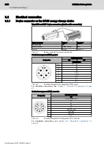
The pin assignment of the connector is shown in
For additional information on the temperature sensor, please refer to
9.9 "Thermal winding protection" on page 43
.
8.6
Cooling
8.6.1
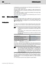
Fan connection
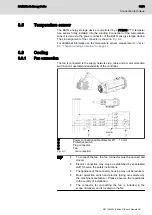
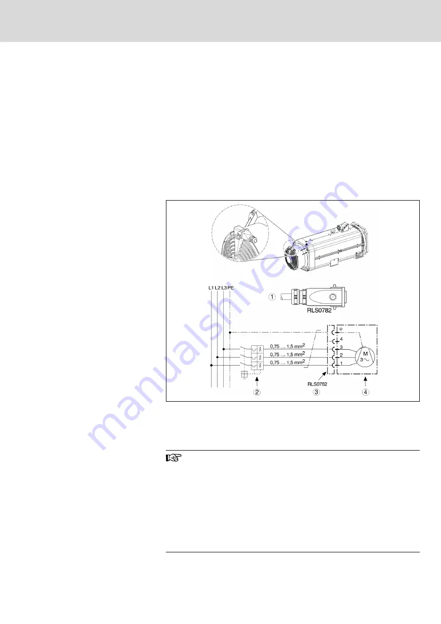
The fan is connected to the supply network via a cable and a motor protective
switch and is operated independently of the controller.
①
Power connection cable diameter Ø 7 ... 10 mm
②
Protective switch
①
Plug connector
①
Fan
Fig. 8-1:
Fan connection
●
To connect the fan, the fan connector must be opened and
closed.
●
Electric connection may only be established by specialized
staff. Observe the safety instructions.
●
The tightness of the connector housing may not be reduced.
●
Motor protective switch and electric fusing are selected by
the machine manufacturer. Please observe the regulations
in the country of installation.
●
The connector for connecting the fan is included in the
scope of delivery and is located on the fan.
BA1N Kinetic Energy Buffer
31/73
Connection technique
R911393264_Edition 01 Bosch Rexroth AG
Summary of Contents for Rexroth BA1N
Page 1: ...BA1N Kinetic Energy Buffer Project Planning Manual R911393264 Edition 01 ...
Page 30: ...24 73 BA1N Kinetic Energy Buffer Bosch Rexroth AG R911393264_Edition 01 ...
Page 32: ...26 73 BA1N Kinetic Energy Buffer Bosch Rexroth AG R911393264_Edition 01 ...
Page 40: ...34 73 BA1N Kinetic Energy Buffer Bosch Rexroth AG R911393264_Edition 01 ...
Page 52: ...46 73 BA1N Kinetic Energy Buffer Bosch Rexroth AG R911393264_Edition 01 ...
Page 62: ...56 73 BA1N Kinetic Energy Buffer Bosch Rexroth AG R911393264_Edition 01 ...
Page 74: ...68 73 BA1N Kinetic Energy Buffer Bosch Rexroth AG R911393264_Edition 01 ...
Page 77: ...Notes BA1N Kinetic Energy Buffer 71 73 ...
Page 78: ...Notes 72 73 BA1N Kinetic Energy Buffer ...

