background image

900

1000

1100

1200

1300

1400

1500

1600

1700

0

10

20

30

40

50

60

70

80

90

100

110

120

130

140

150

160

170

O

h

m

°C

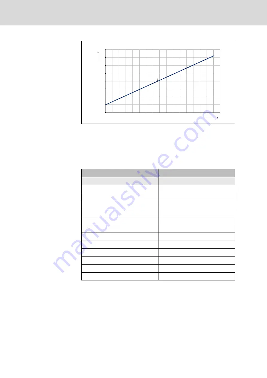
PT1000

R

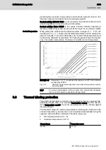
Fig. 9-6:

Characteristic curve PT1000

Please  observe  the  notes  about  connecting  the  temperature  sensor  in 

the

chapter "Connecting technique"

.

9.10 

Encoder

9.10.1 

Technical data

Encoder option

AS

Design

Singleturn

Protocol

Hiperface®

Signal periods

16

Resolution

-

Distinguishable rotations

1

System accuracy typical / maximum

±360´´ / ±520´´

Data transmission

analog 1 Vpp

Supply voltage

7 ... 12 V

Current consumption

< 50 mA

Functional safety EN IEC 61508 

-

Functional safety EN ISO 13849

-

Single cable connection

-

Double cable connection

● / -

available/not available

Tab. 9-9:

Technical data of encoder

9.10.2 

Encoder connection

The position of the encoder connector on the energy storage device cannot

be changed. Notes on connecting the encoder can be found in 

tab. 8-1 "De‐

vice connector for power and encoder" on page 28

.

For detailed information on the controller-side encoder connection, please re‐

fer to the documentation of the controllers.

44/73

Application notes

 BA1N Kinetic Energy Buffer

Bosch Rexroth AG R911393264_Edition 01

Summary of Contents for Rexroth BA1N

Page 1: ...BA1N Kinetic Energy Buffer Project Planning Manual R911393264 Edition 01 ...

Page 2: ... event of applications for industrial prop erty rights Liability The specified data is intended for product description purposes only and shall not be deemed to be a guaranteed characteristic unless expressly stipulated in the contract All rights are reserved with respect to the content of this docu mentation and the availability of the product Published by Bosch Rexroth AG Electric Drives and Con...

Page 3: ...regard to specific dangers 10 3 3 1 Protection against contact with electrical parts and housings 10 3 3 2 Protective extra low voltage as protection against electric shock 11 3 3 3 Protection against dangerous movements 12 3 3 4 Protection against electromagnetic and magnetic fields during operation and mounting 13 3 3 5 Protection against contact with hot parts 14 3 3 6 Protection during handlin...

Page 4: ...t connection 32 8 6 3 Coolant input pressure 33 9 Application notes 35 9 1 Operating conditions 35 9 1 1 Installation altitude and ambient temperature 35 9 2 Humidity 36 9 3 Vibration and shock 36 9 3 1 Vibration 36 9 3 2 Shock 37 9 4 Degree of protection 37 9 5 Frame shape and installation position 38 9 5 1 General 38 9 6 Paint 38 9 7 Compatibility test 39 9 8 Cooling 39 9 8 1 Forced ventilation ...

Page 5: ...55 12 Operation of BA1N energy storage device 57 12 1 Commissioning 57 12 1 1 General 57 12 1 2 Preparation 57 12 1 3 Procedure 57 12 2 Shutdown 58 12 3 Disassembly 58 12 4 Maintenance 59 12 4 1 General 59 12 4 2 Measures 59 12 4 3 Re lubrication of the hybrid bearings 60 12 4 4 Fan 61 12 4 5 Coolant supply 63 12 5 Troubleshooting 63 12 5 1 General information 63 12 5 2 Temperature on the housing ...

Page 6: ...Page 13 Service and support 67 Index 69 IV 73 Table of Contents BA1N Kinetic Energy Buffer Bosch Rexroth AG R911393264_Edition 01 ...

Page 7: ...can be found in the Application Manual un der MLD Technology Function Kinetic Buffering R911397139 in the Rexroth media directory see chapter 1 2 4 Further documentation on page 3 Example applications Power failure buffering Mains side peak power reduction Mains quality improvement Reduction of connection power Increase of energy efficiency in feeding systems with braking resistor Booster for incr...

Page 8: ...sories 8 Connection technology Practice 9 Application instructions 10 Handling and transport for operating and maintenance per sonnel 11 Installation 12 Operation 13 Service support Additional information 14 Index Tab 1 2 Chapter structure 1 2 3 Information presentation Safety instructions The safety instructions in this documentation include signal words danger warning caution note and a signal s...

Page 9: ... with cardiac pacemakers or implanted defibrilla tors Do not carry along metal parts or clocks Tab 1 3 Meaning of safety signs Markup The following markups are used for a user friendly text information represen tation Reference to supplementary documentation This note gives important information which must be observed Listings on the first level contain a bullet point Listings on the second level ...

Page 10: ... 10787 Berlin Germany Tel 49 0 30 26 01 22 60 Fax 49 0 30 26 01 12 60 Internet http www din de beuth Email postmaster beuth de 1 2 6 Additional components Documentation for external systems which are connected to Bosch Rexroth components are not included in the scope of delivery and must be ordered directly from the corresponding manufacturers 1 2 7 Your feedback Your experiences are an essential ...

Page 11: ...code must not be changed Damaged or defective products must not be installed or put into opera tion It must be ensured that products are installed in compliance with all reg ulations specified in the documentation 2 1 2 Areas of use and application BA1N energy storage devices are designed to be used as kinetic energy stor age devices The following are typical fields of application Mains power peak...

Page 12: ...ating conditions and technical data other than those specified in this documentation is considered as unintended use BA1N energy storage devices may not be used if they are exposed to operating conditions that do not meet the specified ambient conditions This includes for example operation under water under extreme temperature fluctuations or extreme maximum tempera tures the intended fields of ap...

Page 13: ...responding lines and ca bles Installation An installation consists of several devices or systems interconnected for a defined purpose and on a defined site which however are not intended to be placed on the market as a single functional unit Machine A machine is the entirety of interconnected parts or units at least one of which is movable Thus a machine consists of the appropriate machine drive e...

Page 14: ...nent is resold rented and or passed on to others in any other form these safety instructions must be delivered with the component in the official language of the user s country Improper use of these components failure to follow the safety instructions in this document or tampering with the product including disabling of safety de vices could result in property damage injury electric shock or even ...

Page 15: ...e that the machine or installation in which the components are instal led complies with the national regulations safety specifications and standards of the application Operation is only allowed if the national EMC regulations for the applica tion are met The instructions for installation in accordance with EMC requirements can be found in the section on EMC in the respective application docu menta...

Page 16: ...wed to operate maintain and or repair the components of the electric drive and control system Follow the general installation and safety regulations when working on power installations Before switching on the equipment grounding conductor must have been permanently connected to all electric components in accordance with the connection diagram Even for brief measurements or tests operation is only ...

Page 17: ...able below With an outer conductor cross sec tion smaller than 10 mm2 8 AWG the alternative connection of two equipment grounding conductors is allowed each having the same cross section as the outer conductors Cross section outer con ductor Minimum cross section equipment grounding conductor Leakage current 3 5 mA 1 equipment grounding conductor 2 equipment grounding conductors 1 5 mm2 16 AWG 10 ...

Page 18: ...fety especially the danger of injury and or property damage this alone cannot be relied upon to ensure complete safety Until the integrated monitoring functions become effective it must be as sumed in any case that faulty drive movements will occur The extent of faulty drive movements depends upon the type of control and the state of opera tion Dangerous movements Danger to life risk of injury ser...

Page 19: ...tinued equipment use Prevent the operation of high frequency remote control and radio equip ment near components of the electric drive and control system and their supply leads If the use of these devices cannot be avoided check the machine or installation at initial commissioning of the electric drive and control system for possible malfunctions when operating such high fre quency remote control ...

Page 20: ...at the machine or in stallation guards shieldings or barriers or safety instructions in the ap plication documentation 3 3 6 Protection during handling and mounting Risk of injury by improper handling Injury by crushing shearing cutting hit ting Observe the relevant statutory regulations of accident prevention Use suitable equipment for mounting and transport Avoid jamming and crushing by appropri...

Page 21: ...quids and cooling lubricants Improper handling of the connected supply systems supply lines or connections can cause injuries or property damage Risk of injury by improper handling of pressurized lines Do not attempt to disconnect open or cut pressurized lines risk of ex plosion Observe the respective manufacturer s operating instructions Before dismounting lines relieve pressure and empty medium ...

Page 22: ...tion point which pre cedes the signal words DANGER WARNING and CAUTION is used to alert the reader to personal injury hazards DANGER In case of non compliance with this safety instruction death or serious injury will occur WARNING In case of non compliance with this safety instruction death or serious injury could occur CAUTION In case of non compliance with this safety instruction minor or modera...

Page 23: ...ousing Unit nF Number of pole pairs p number of pole pairs of the storage device Power wire cross section A Unit mm Rated for cables by current carrying capacity according to VDE 0298 4 and laying type B2 according to EN 60204 1 at a surrounding air tem perature of 40 C Other installation methods or higher ambient temperatures may require a higher power wire cross section Mass m mass of the energy...

Page 24: ...emperature during operation Tum C 0 40 Thermal class according to DIN EN 60034 1 I CL 155 Information on DC bus voltage 540 VDC Continuous power3 PC kW 42 5 32 0 Maximum power3 Pmax kW 90 2 122 4 Energy content for nPN EnPN kJ 130 8 Speed range for energy content EnPN nRange_PN min 1 2000 6000 Energy content for nPmax EnPmax kJ 72 9 27 1 Speed range for energy content EnPmax nRange_Pmax min 1 1770...

Page 25: ...r Symbol Unit Value Voltage type 3 AC Air flow direction blowing Medium volume current m3 h 520 0 Nominal voltage UN V 400 480 Nominal frequency f Hz 50 60 50 60 Fan current 1 IN A 0 21 0 26 0 28 0 25 Blocking current Iblock A 0 64 0 6 0 76 0 73 Power consumption SN VA 145 180 233 208 1 Fan current monitoring should start at IN 20 Tab 4 2 Data sheet BA1N16 fan 4 2 3 Water cooling Technical data Pa...

Page 26: ... characteristic curves Fig 4 1 BA1N16 characteristic curve forced ventilation Fig 4 2 BA1N16 characteristic curve water cooling 20 73 Technical data BA1N Kinetic Energy Buffer Bosch Rexroth AG R911393264_Edition 01 ...

Page 27: ...imension sheets 5 1 BA1N16 Frame size with cooling mode forced ventilation Fig 5 1 Dimension sheets BA1N16 with fan BA1N Kinetic Energy Buffer 21 73 Dimension sheets R911393264_Edition 01 Bosch Rexroth AG ...

Page 28: ...5 2 BA1N16 Frame size with cooling mode water cooling Fig 5 2 Dimension sheets BA1N16 with water cooling 22 73 Dimension sheets BA1N Kinetic Energy Buffer Bosch Rexroth AG R911393264_Edition 01 ...

Page 29: ...6 Type codes 6 1 Type codes BA1N16 Fig 6 1 Type codes BA1N16 BA1N Kinetic Energy Buffer 23 73 Type codes R911393264_Edition 01 Bosch Rexroth AG ...

Page 30: ...24 73 BA1N Kinetic Energy Buffer Bosch Rexroth AG R911393264_Edition 01 ...

Page 31: ...7 Accessories For BA1N no accessories are available BA1N Kinetic Energy Buffer 25 73 Accessories R911393264_Edition 01 Bosch Rexroth AG ...

Page 32: ...26 73 BA1N Kinetic Energy Buffer Bosch Rexroth AG R911393264_Edition 01 ...

Page 33: ...ion was rated for cables by current carrying capaci ty according to VDE 0298 4 and laying type B2 according to EN 60204 1 at an ambient temperature of 40 C Significant advantages of Rexroth s ready made cables are Ready for connection without any additional finishing Designed for continuous alternating bending stress Resistant against mineral oil grease and bio oil silicone and halogen free low ad...

Page 34: ... Ax Bx without brake U1 A1 V1 A2 W1 A3 PE 5 TP 6 TP 7 n c 8 n c 9 n c Tab 8 2 Contact arrangement pin assignment M58 power For installation instructions see chapter 8 Connection technique on page 27 Contact arrangement M17 encoder Designation Encoder connection AS 1 VCC_Encoder 11V 2 B 3 B 4 A 5 A 6 GND_Encoder 7 EncData 8 EncData 9 n c Tab 8 3 Contact arrangement pin assignment M17 encoder For in...

Page 35: ...coder cable 8 3 Plug in connector with threaded connection Damage to persons or property by discon necting or connecting energized connectors WARNING Connect and disconnect connectors only when they are dry and de energized During operation of the system all connectors must be securely tight ened or locked Observe when connecting the flange sockets Protect the flange sockets from external force ef...

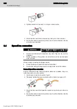
Page 36: ... or locked Observe when connecting the flange sockets Protect the flange sockets from external force effect Connect the energy storage device to ready made connection cables Connect SpeedCon connectors Properly measured ready made connection cables are available Plug con nector type size wire cross section 1 Insert power connector in position open 2 Manually tighten the power connector with a rota...

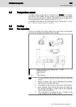
Page 37: ...ective switch and is operated independently of the controller Power connection cable diameter Ø 7 10 mm Protective switch Plug connector Fan Fig 8 1 Fan connection To connect the fan the fan connector must be opened and closed Electric connection may only be established by specialized staff Observe the safety instructions The tightness of the connector housing may not be reduced Motor protective s...

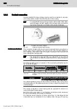
Page 38: ...e vice The following table gives an overview of the maximum permissible load on the connection threads Size BA1N Connection thread max permissible screw in depth mm max permissible tightening range Nm 16 G1 2 18 27 30 Tab 8 6 Cooling connection thread permissible tightening torque and screw in depth The coolant port threads on the housing may be destroyed by incorrect tightening torques NOTICE The...

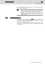
Page 39: ...olant connection should be logged in the maintenance sched ule of the machine 8 6 3 Coolant input pressure The maximum coolant input pressure of 6 bar applies to all BA1N energy storage devices based on the effective current pressure directly at the cool ant connection on the energy storage device Please observe that additional screw connections or junctions in the cooling circuit can have a negat...

Page 40: ...34 73 BA1N Kinetic Energy Buffer Bosch Rexroth AG R911393264_Edition 01 ...

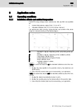
Page 41: ...actor tA Ambient temperature in degrees Celsius fH Height utilization factor h Installation altitude in meters Fig 9 1 Utilization factors If either the ambient temperature or the installation altitude is above the nomi nal data 1 Multiply the data specified in the selection data by the determined uti lization factor 2 Ensure that the reduced data are not exceeded by your application If both the a...

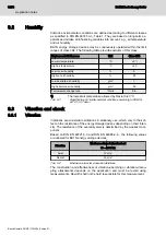
Page 42: ...assification of climatic ambient conditions according to DIN EN 60721 3 3 Table 1 9 3 Vibration and shock 9 3 1 Vibration Vibrations are sinusoidal oscillations in stationary use which vary in their ef fect on the resistance of the energy storage devices depending on their inten sity The resistance of the overall system is determined by the weakest com ponent Based on DIN EN 60721 3 3 and DIN EN 6...

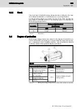
Page 43: ...s are subject to the degrees of protection pur suant to IEC 60529 It must always be ensured that the energy storage devi ces irrespective of their installation position are not exposed to ambient conditions outside of the applicable degree of protection Fig 9 2 Component subject to protection Degree of protection Remark Motor fan only for force ventilated versions IP 65 Fan motor IP 65 Fan grille ...

Page 44: ...y storage device 9 6 Paint Color Black RAL9005 Resistance Resistant against Diluted acids lyes Water seawater sewage Current mineral oils Resistant to a limited degree against Organic solvents Hydraulic oil Not resistant against Concentrated acids lyes Additional paint Allowed for Standard products The housing may be painted with a coating thickness of no more than 40 µm Before painting the housin...

Page 45: ...hich air stream is guided through air baffles over the surface of the energy storage device The fan is designed to use clean air from its surroundings for cooling If the energy storage devices are used in heavily soiled or hazardous areas spe cial precautions must be taken The use of the fan under the following conditions is expressly not suitable Delivery of air which contains abrasive particles ...

Page 46: ...th does not claim any warranty for third party products Rittal GmbH Co KG http www rittal com KKT Kraus Kälte und Klimatechnik GmbH http www kkt chillers com Glen Dimplex Deutschland GmbH http www riedel cooling com BKW Kälte Wärme Versorgungstechnik GmbH http www bkw kuema de Hyfra Industriekühlanlagen GmbH http www hyfra de Tab 9 6 Manufacturers of cooling units The cooling unit must be able to ...

Page 47: ...ing system Coolants The coolant must comply with certain criteria and treated accordingly seetab 9 7 Coolant characteristics on page 42 To ensure corrosion protection and chemical stabilization an additive must be admixed to the cooling water The selected coolant additives biocides inhibitors must comply with the ma terials in the cooling system e g copper brass stainless steel etc and minimize th...

Page 48: ...ent and does not conduct any surveys regarding the suitability of device specif ic cooling media additives or operating conditions and does not assume any warranty for third party products The performance test for the used cooling media and the design of the liquid cooling system is the responsibility of the machine manufacturer The selected coolant additives have to comply with the materials with...

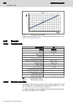
Page 49: ...humidity and air temperature Example Saturation 15 3 C at ambient temperature of 25 C and relative air humidity of 55 Fig 9 5 Saturation temperature depends from ambient temperature and rela tive air humidity To avoid condensation of the motors the coolant inlet tempera ture must be below the saturation temperature 9 9 Thermal winding protection The winding temperature is monitored by two systems ...

Page 50: ...on analog 1 Vpp Supply voltage 7 12 V Current consumption 50 mA Functional safety EN IEC 61508 Functional safety EN ISO 13849 Single cable connection Double cable connection available not available Tab 9 9 Technical data of encoder 9 10 2 Encoder connection The position of the encoder connector on the energy storage device cannot be changed Notes on connecting the encoder can be found in tab 8 1 D...

Page 51: ... down and follow up time of the rotor Special cases errors may occur which lead to the energy storage device not being actively decelerated In this case a run down time of at least 4 minutes must be expected before the rotor inside the energy storage device comes to a standstill 9 13 Acceptances and approvals 9 13 1 CE mark Declarations of conformity confirming the design and compliance with the v...

Page 52: ...46 73 BA1N Kinetic Energy Buffer Bosch Rexroth AG R911393264_Edition 01 ...

Page 53: ...s of shaft end and mounting flange according to DIN 42955 Vibration measurement according to DIN 2373 10 1 3 Customer test Since all BA1N energy storage devices undergo a standardized test proce dure high voltage tests on the customer side are not required BA1N energy storage devices could be damaged if they are subjected to repeated high voltage tests Destruction of the components due to im prope...

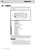
Page 54: ...Serial number 21 Material number Fig 10 1 BA1N type plate example BA1N energy storage devices are each delivered with 2 type plates Attach the second type plate to an easily visible position at the machine This way you can read the data at any time without having to work in areas that are difficult to access and where the energy storage device may be attached Attach type plate 1 Find an easily acc...

Page 55: ... the BA1N energy storage device out of the transport crate or to install it in the machine use the attached lifting eyebolts The lifting eyebolts at least meet the requirements of DIN 580 Before each transport ensure that the lifting eyebolts have been screwed down fully to the contact surface and that your selected lifting equipment and lifting method does not overstress the lifting eyebolts Plea...

Page 56: ...f the particular class However Bosch Rexroth reserves the right to adjust these values at any time based on future experiences or changed environmental factors Allowed transport conditions Environmental factor Symbol Unit Value Temperature TT C 20 801 Air humidity relative air humidity cannot be com bined with a quick temperature change φ 75 at 30 C Occurrence of salt mist Not permitted 1 1 Differ...

Page 57: ...f climatic ambient conditions 1K2 Classification of biological ambient conditions 1B1 Classification of chemically active materials 1C2 Classification of mechanically active materials 1S1 Classification of mechanical ambient conditions 1M2 Tab 10 3 Allowed classes of ambient conditions during storage For a better overview some essential environmental influencing variables of the previously mention...

Page 58: ...e hybrid bearings on page 60 Let the BA1N energy storage device run in without load for one hour at 800 1000 rpm 5 years Send the BA1N energy storage device back to the Bosch Rexroth service for overhaul e g bearing or encoder replace ment Tab 10 5 Measures before commissioning BA1N energy storage devices that have been stored over a prolonged period of time Cable and plug connector storage times ...

Page 59: ...ps with particular care This minimizes the risk of acci dents and damage 11 2 Mechanical attachment 11 2 1 Attachment Fastening screws To attach the energy storage devices properly and safely to the machine Bosch Rexroth recommends the following screws and washers for attach ment Frame size BA1N16 Hexagon head screws DIN EN ISO 4014 or Cylinder head screws DIN EN ISO 4762 and Washer DIN EN ISO 709...

Page 60: ...MA Nm at µG0 12 BA1N16 14 M12 84 Rz32 MA Tightening torque in newton meter µG Friction coefficient Tab 11 1 Mounting holes and tightening torque of the screws Foot mounting The following procedure is recommended for foot mounting 1 Dismount the protective covers attached to the mounting feet to have free access to the mounting holes 2 Adjust the energy storage device so that the mounting feet matc...

Page 61: ...ss 11 2 3 Mounting the BA1N energy storage device Connect the energy storage device to the machine observe tightening tor ques Check whether the connection is firm and accurate before carrying out any further steps After proper mechanical assembly carry out the electrical connection 11 3 Electrical connection 11 3 1 General Use ready made connection cables by Bosch Rexroth These cables have numero...

Page 62: ...56 73 BA1N Kinetic Energy Buffer Bosch Rexroth AG R911393264_Edition 01 ...

Page 63: ...hanical and electrical connections 5 Activate the safety and monitoring equipment of the system 12 1 3 Procedure Once all requirements are met proceed as follows 1 Activate the fan or the external cooling system supplying the BA1N en ergy storage device and check them to verify that they are in a proper condition Comply with the manufacturer s instructions 2 Commission the drive system according t...

Page 64: ...moving elements WARNING Work on machines is only allowed if they are secured and while they are not running Switch off the controller and the machine and wait until the discharging time of the electrical systems has elapsed before starting troubleshoot ing Before starting disassembly secure the machine against unforeseeable movements and against unauthorized operation Before disassembling the moto...

Page 65: ...or be used by unauthorized persons Do not work on hot surfaces Bosch Rexroth recommends the following maintenance measures based on the maintenance plan of the machine manufacturer Measure Interval For water cooled energy storage devices Check the cooling system for proper functioning According to the specifications in the machine maintenance plan but at least every 1000 ope rating hours For force...

Page 66: ...mitted grease quantity in order not to exceed this quantity The grease must be pumped in slowly and carefully during operation at a low speed of 100 rpm so that the bearing is not overheated due to re lubrication Re lubrication of the bearings must only be carried out 4 times If the end of the available operating hours see Re lubrica tion instruction sign of the last re lubrication interval has be...

Page 67: ...burns CAUTION Ensure adequate contact protection and wait until the energy storage device has cooled down Ensure that there are no combustible and flammable materials in the en vironment of the hot fan Risk of injuries While voltage is applied the energy storage device restarts automatically e g after a power failure CAUTION Do not stay within the danger zone of the device When working on the devi...

Page 68: ...ce schedule however at least every 6 months Attachment of connecting lines Lining of contact protection Fan for damage Attachment of fan Tab 12 2 Visual fan inspection Notes on troubleshooting Failure fault Possible cause Possible action Fan motor not running Mechanical blockage Switch off and de energize the energy storage device and re move the mechanical blockage Wrong line voltage Check the li...

Page 69: ... Cooling circuit or fan function and temperature behavior Internal temperature sensor Encoder or encoder connection Mechanical damage of the BA1N energy storage device Mechanical connection to machine The encoder connection and the temperature sensor are monitored by the controller or the control unit corresponding diagnostic messages are dis played Comply with the instructions in the correspondin...

Page 70: ...ding to the interconnection diagram 4 Failure of the temperature sensor PTC Measures for 1 Check the resistance value of the temperature sensor using a multime ter 2 Check the diagnostic system at the controller or the control unit 3 Set the measuring device to resistance measurement mode Shut down the system and wait until the discharging time has elapsed Disconnect the temperature sensor from th...

Page 71: ... the following address Bosch Rexroth AG Electric Drives and Controls Buergermeister Dr Nebel Straße 2 97816 Lohr am Main Germany Packaging Packaging materials consist of cardboard wood and polystyrene They can be recycled anywhere without any problem For ecological reasons please refrain from returning the empty packages to us Batteries and accumulators Batteries and accumulators can be labeled wi...

Page 72: ...stic parts of the products may contain flame retardants These plastic parts are labeled according to EN ISO 1043 They have to be recycled sepa rately or disposed of according to the applicable legal provisions 66 73 Operation of BA1N energy storage device BA1N Kinetic Energy Buffer Bosch Rexroth AG R911393264_Edition 01 ...

Page 73: ...hrexroth com Additional information on service repair e g delivery addresses and training can be found on our internet sites Service worldwide Outside Germany please contact your local service office first For hotline numbers refer to the sales office addresses on the internet Preparing information To be able to help you more quickly and efficiently please have the following information ready Deta...

Page 74: ...68 73 BA1N Kinetic Energy Buffer Bosch Rexroth AG R911393264_Edition 01 ...

Page 75: ...water cooling 22 Disassembly 58 Discharge capacity 17 Discharging time 58 Disposal 65 Drive system 7 E Electric drive system 7 Electrical connection 55 Encoder 44 Connection 44 Energy content 17 Energy efficiency 19 Environmental protection 65 F Factory test 47 Fan 19 61 Fan current monitoring 19 Maintenance 61 Troubleshooting 62 Fault states 63 foot mounting 54 Frame shape 38 H handling 47 Hazard...

Page 76: ...lectric drives and controls 7 Service hotline 67 Shock 37 Shutdown 58 Shutdown temperature 43 Significant components 65 Sound pressure level 17 Standards 4 Storage 49 Storage conditions 51 Strength 55 Support 67 T Temperature sensor 43 Test High voltage test 47 Insulation resistance 47 Protective conductor 47 Thermal time constant 17 Transport 49 Transport conditions 50 Troubleshooting 63 U Use in...

Page 77: ...Notes BA1N Kinetic Energy Buffer 71 73 ...

Page 78: ...Notes 72 73 BA1N Kinetic Energy Buffer ...

Page 79: ...Notes BA1N Kinetic Energy Buffer 73 73 ...

Page 80: ... Electric Drives and Controls P O Box 13 57 97803 Lohr Germany Bgm Dr Nebel Str 2 97816 Lohr Germany Phone 49 9352 18 0 Fax 49 9352 18 8400 www boschrexroth com electrics R911393264 R911393264 DOK MOTOR BA1N PR01 EN P ...

Reviews: