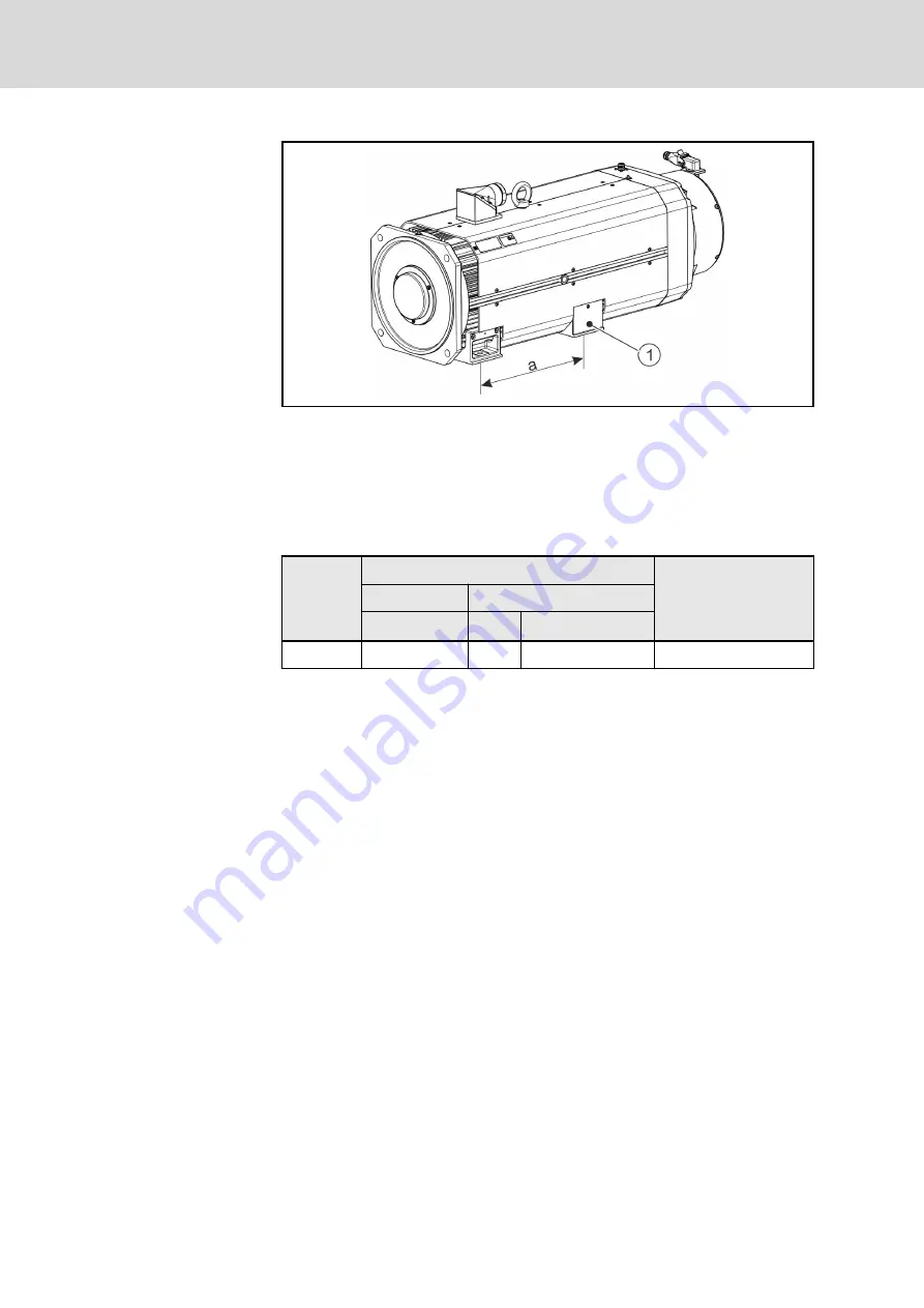
Attachment types
①
Mounting feet (4 pcs.) for foot mounting
a
For clearance "a”, see dimension sheet
Fig. 11-1:
Attachment of BA1N
BA1N energy storage devices are factory-prepared for foot mounting. The
particular dimension drawing contains details on the size and position of the
mounting holes. In general, the following assignment is applicable for attach‐
ing the motors:
Size
B35 (foot mounting)
Peak-to-valley height of
the mounting surface to
the machine
Hole
Screw (8.8)
Ø [mm]
Type
M
A
[Nm] at µ
G
0.12
BA1N16
14
M12
84
Rz32
M
A
Tightening torque in newton meter
µ
G
Friction coefficient
Tab. 11-1:
Mounting holes and tightening torque of the screws
Foot mounting
The following procedure is recommended for foot mounting:
1.
Dismount the protective covers attached to the mounting feet to have
free access to the mounting holes.
2.
Adjust the energy storage device so that the mounting feet match the at‐
tachment points of the machine.
3.
Firmly connect the energy storage device to the machine (for tightening
torques, see
4.
Reattach the protective covers to the mounting feet.
54/73
Installation
BA1N Kinetic Energy Buffer
Bosch Rexroth AG R911393264_Edition 01
Summary of Contents for Rexroth BA1N
Page 1: ...BA1N Kinetic Energy Buffer Project Planning Manual R911393264 Edition 01 ...
Page 30: ...24 73 BA1N Kinetic Energy Buffer Bosch Rexroth AG R911393264_Edition 01 ...
Page 32: ...26 73 BA1N Kinetic Energy Buffer Bosch Rexroth AG R911393264_Edition 01 ...
Page 40: ...34 73 BA1N Kinetic Energy Buffer Bosch Rexroth AG R911393264_Edition 01 ...
Page 52: ...46 73 BA1N Kinetic Energy Buffer Bosch Rexroth AG R911393264_Edition 01 ...
Page 62: ...56 73 BA1N Kinetic Energy Buffer Bosch Rexroth AG R911393264_Edition 01 ...
Page 74: ...68 73 BA1N Kinetic Energy Buffer Bosch Rexroth AG R911393264_Edition 01 ...
Page 77: ...Notes BA1N Kinetic Energy Buffer 71 73 ...
Page 78: ...Notes 72 73 BA1N Kinetic Energy Buffer ...

