

R911418823, Edition 01, 2 / 8
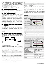
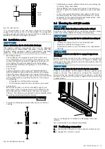
3.3 Internal schematic diagram
A/D
System bus
U
L
U
P
µC
AI_1
.
.
.
.
U
P
24 V
DC/DC
AI_4
Fig. 2: Internal schematic diagram
3.4 Ambient conditions
XI342204
Ambient temperature
Up to 4000 m
From 4000 m
Maximum operating altitude
Acc. to 60204
-25 to 45 °C
-25 to 40 °C
5000 m
Ambient temperature
(Storage and transport)
-40 to 70 °C
Permitted air humidity
according to DIN EN 61131-2
Operation
Storage
Transport
5-85 %
10-100 %
45-95 %
Degree of protection
Acc. to DIN EN 60 529
IP20
(not evaluated by UL)
Protection class
Acc. to DIN EN 61010-2-201
III
Overvoltage category
Acc. to IEC 60664-1
2
Contamination level
Acc. to IEC 61010-1
2, no condensation
NOTICE
Failure of the product due to contaminated air!
−
The ambient air must not contain acids, alkaline solu-
tions, corrosive agents, salts, metal vapors and other
electrically conductive contaminants in high concentra-
tions.
−
The devices to be installed into the housing and installa-
tion compartments must at least comply with the degree
of protection IP 54 according to DIN EN 60529.
−
The device shall be provided in a suitable fire enclosure
in the end-use application.
NOTICE
Defective product due to gases jeopardizing functions
Due to the risk of corrosion, avoid sulphurous gases (e.g.
sulphur dioxide (SO
2
) and hydrogen sulphide (H
2
S)). The
product is not resistant against these gases.
NOTICE
Failure of the product due to overheating
To avoid overheating and a trouble-free operation of the
product, the ambient air has to circulate. Also refer to the
section “Installation notes”.
3.5 Mechanical tests
Vibration resistance
Acc. to DIN EN 60068-2-6
Oscillations, sinusoidal in all
three axes, 5 Hz - 8.4 Hz with
3.5 mm amplitude
8.4 Hz -150 Hz with 1 g peak
acceleration
Shock test
Acc. to DIN EN 60068-2-27
Shock stress: Shock resist-
ance in all three axes
11 ms semi-sinusoidal 15 g
Broadband noise
Acc. to DIN EN 60068-2-64
20-500 Hz with 1.22 g RMS,
30 min in all three axes
For the current approvals, go to
www.boschrexroth.com/electrics.
4
For your safety
4.1 Intended use
Only use the module as specified in the data sheet.
4.2 User qualification
The product use described in this data sheet is only intended
for qualified electricians and staff trained by these qualified
electricians. The user has to be familiar with the known safety
concepts on automation technology, applicable standards and
other guidelines.
4.3 Electric safety
NOTICE
Loss of electric safety
Unintended handling can affect the device safety! Observe
the notes in the present data sheet during installation, com-
missioning and operation.
5
Signal processing
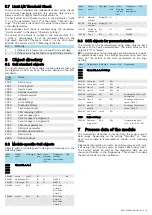
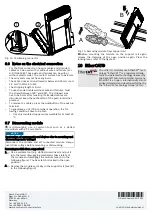
5.1 General information on signal processing
The signal processing of the module consists of several steps
shown in this section, i.e. how low-pass filter and oversam-
pling are implemented in hardware components while other
steps are implemented as firmware functions.
Value range
limit
User gain,
offset
Status
information
output to
EtherCAT
Digitalization
with
oversampling
in ADC
HW filter
Low-Pass
Limit 1/2
threshold
check
Over-,
underrange
threshold
check
ADC Raw
value
(CoE object)
ADC input,
transfer to µC
Process data
output to
EtherCAT
Fig. 3: Overview on signal processing
5.2 Distinctive values and data formats
Input signal
Process data
value
Percent,
measuring
range
Notes
Voltage in V
Voltage in mV
10.8
10800
108%
Message, upper range
limit
10.7
10700
107%
Reset message, upper
range limit
10
10000
100%
0
0
0%
Value limitation down
to 0 V
-0.05
0
Reset message, lower
range limit
-0.15
0
Message, lower range
limit
Process data is transferred as value normalized to mV in
"signed int 16" format. The process date corresponds directly
to the values read in at the input. It depends on the gain and
offset calculation. Thus, the conversion to an abstract value
range is omitted. The value can be directly used as voltage
value in the application.


