background image

R911418823, Edition 01, 5 / 8

Process data consists of the value and the diagnostic data in

the standard representation:

Word 1

INT

IN

Channel 1 Value

Word 2


Byte 1


Bit 0
Bit 1
Bit 2-3
Bit 4-5

IN
IN
IN
IN
IN
IN


Channel 1 Wire break
Channel 1 Overrange
Channel 1 Limit 1
Channel 1 Limit 2

Word 3

INT

IN

Channel 2 Value

Word 4


Byte 1


Bit 0
Bit 1
Bit 2-3
Bit 4-5

IN
IN
IN
IN
IN
IN


Channel 2 Wire break
Channel 2 Overrange
Channel 2 Limit 1
Channel 2 Limit 2

Word 5

INT

IN

Channel 3 Value

Word 6


Byte 1


Bit 0
Bit 1
Bit 2-3
Bit 4-5

IN
IN
IN
IN
IN
IN


Channel 3 Wire break
Channel 3 Overrange
Channel 3 Limit 1
Channel 3 Limit 2

Word 7

INT

IN

Channel 4 Value

Word 8


Byte 1


Bit 0
Bit 1
Bit 2-3
Bit 4-5

IN
IN
IN
IN
IN
IN


Channel 4 Wire break
Channel 4 Overrange
Channel 4 Limit 1
Channel 4 Limit 2

Word 9


Byte 1


Bit 0
Bit 1

IN
IN
IN
IN


Periphery voltage ok
Error

Table 1: Standard representation

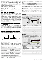
To directly arrange the status bits one after another and thus

to  reduce  the  amount  of  filling  bites,  select  "Channel  x  com-

pact" as well as "Device state compact" in the Engineering.
Process  data  consists  of  the  input  value  and  the  diagnostic

data in the "Compact" representation:

Word 1

INT

IN

Channel 1 Value

Word 2

INT

IN

Channel 2 Value

Word 3

INT

IN

Channel 3 Value

Word 4

INT

IN

Channel 4 Value

Word 5


Byte 1


Byte 2


Bit 0
Bit 1
Bit 2
Bit 3
Bit 4-5
Bit 6-7


Bit 2
Bit 3
Bit 4-5
Bit 6-7

IN
IN
IN
IN
IN
IN
IN
IN
IN
IN
IN
IN


Periphery voltage ok
Error
Channel 1 Wire break
Channel 1 Overrange
Channel 1 Limit 1
Channel 1 Limit 2


Channel 2 Wire break
Channel 2 Overrange
Channel 2 Limit 1
Channel 2 Limit 2

Word 6


Byte 1


Byte 2


Bit 2
Bit 3
Bit 4-5
Bit 6-7


Bit 2
Bit 3
Bit 4-5
Bit 6-7

IN
IN
IN
IN
IN
IN
IN
IN
IN
IN
IN


Channel 3 Wire break
Channel 3 Overrange
Channel 3 Limit 1
Channel 3 Limit 2


Channel 4 Wire break
Channel 4 Overrange
Channel 4 Limit 1
Channel 4 Limit 2

Table 2: "Comact" figure

8

Diagnostic strategy

8.1 Mechanisms

Different  mechanisms  are  used  for  the  diagnostics  of  the

module.

Mechanism

Diagnostics

EtherCAT state machine
EtherCAT hardware watchdog

EtherCAT system diagnostics

Diagnostic objects in the CoE

object directory
10F1

Extended diagnostics, e.g.

peripheral errors
Error settings

Diagnosis history object

10F3

20 diagnostic messages can

be stored
Diagnosis history

Module status LED

Shows the general module

status

Channel status LED

Signals the channel status or

the error states

Summary of Contents for Rexroth ctrlX I/O XI312204

Page 1: ...cal data 3 1 General technical data XI312204 Number of inputs 4 Connection method Push in XI312204 Connection method 2 wire shielded twisted in pairs Signal type Differential Input signal 0 V to 10 V Input resistance 250 kΩ Limit frequency of input filter 12 8 kHz Conversion time 100 μs Resolution D A 16 bits incl sign Accuracy Typ 0 1 of the end value of the measured range MBE Max 0 3 of MBE Over...

Page 2: ...mi sinusoidal 15 g Broadband noise Acc to DIN EN 60068 2 64 20 500 Hz with 1 22 g RMS 30 min in all three axes For the current approvals go to www boschrexroth com electrics 4 For your safety 4 1 Intended use Only use the module as specified in the data sheet 4 2 User qualification The product use described in this data sheet is only intended for qualified electricians and staff trained by these q...

Page 3: ... the gain and the offset Value_Range The value range at the input of the User Scale calculation Scaled_Value_Range The desired value range at the output of the User Scale calculation Lower_Range_End_Value The value at the lower end of the input value range Scaled_Lower_Range_End_Value The desired value at the lower end of the output value range The values for gain and offset are calculated as foll...

Page 4: ... 6010 6020 6030 Channel 1 2 3 4 60x0 01 Value Int16 IN mV 60x0 02 Underrange Bit IN W 0x2360 60x0 03 Overrange Bit IN W 0x8910 60x0 04 Limit 1 2Bit IN Bit0 Value Limit 1 Bit1 Value Limit 1 60x0 06 Limit 2 2Bit IN Bit0 Value Limit 2 Bit1 Value Limit 2 Index hex Object name Data type Direc tion Error warning informa tion Diagnostic number description Unit A000 0 Material number String 20 IN A010 0 F...

Page 5: ...input value and the diagnostic data in the Compact representation Word 1 INT IN Channel 1 Value Word 2 INT IN Channel 2 Value Word 3 INT IN Channel 3 Value Word 4 INT IN Channel 4 Value Word 5 Byte 1 Byte 2 Bit 0 Bit 1 Bit 2 Bit 3 Bit 4 5 Bit 6 7 Bit 2 Bit 3 Bit 4 5 Bit 6 7 IN IN IN IN IN IN IN IN IN IN IN IN Periphery voltage ok Error Channel 1 Wire break Channel 1 Overrange Channel 1 Limit 1 Cha...

Page 6: ...or peripheral voltage error RD RD RD RD RD RD RD RD RD RD Communication or configura tion error RD RD RD RD RD Table 3 Module status LED diagnostic and device status 8 5 Channel status LED Each input channel of the module is provided via a channel status LED at the plug Refer to Chapter 3 2 Clamping point assignment on page 1 Meaning of the channel LED LED Meaning Red Signal error Overrange or und...

Page 7: ...vide the following minimum distances for sufficient cooling 35 mm 0 mm 0 mm 35 mm 35 mm Fig 10 Ventilation distance Additionally provide sufficient distance for mounting dis mounting plugs and cables If more devices are connected in series to the station on the left or right the surface temperature may not exceed 60 C In case of a several line design the supply air has to be measured under each li...

Page 8: ... to be met Use only insulated copper wires suitable for at least 60 C 9 7 Dismounting module For dismounting use a common tool such as a slotted screwdriver with a 2 5 mm blade NOTICE Destruction of components and devices due to mounting and dismounting under voltage Disconnect the module and all connected module compo nents from voltage before mounting or dismounting Removing module from support ...

Reviews: