background image

Email Us

sales@wakeindustrial.com


We ship worldwide,  offering


any type of shipping method


with  all  the  major  logistic


companies  such  as  FedEx,


UPS,  DHL,  USPS,  and  a


variety of freight carriers.


Stay In Touch

Wake Industrial, LLC


1620 Old Apex Road


Cary, NC 27513

Call:


1-888-551-3082


International:1-919-443-0207

Fax:1-919-267-1705

Email:


sales@wakeindustrial.com

Website:


www.wakeindustrial.com

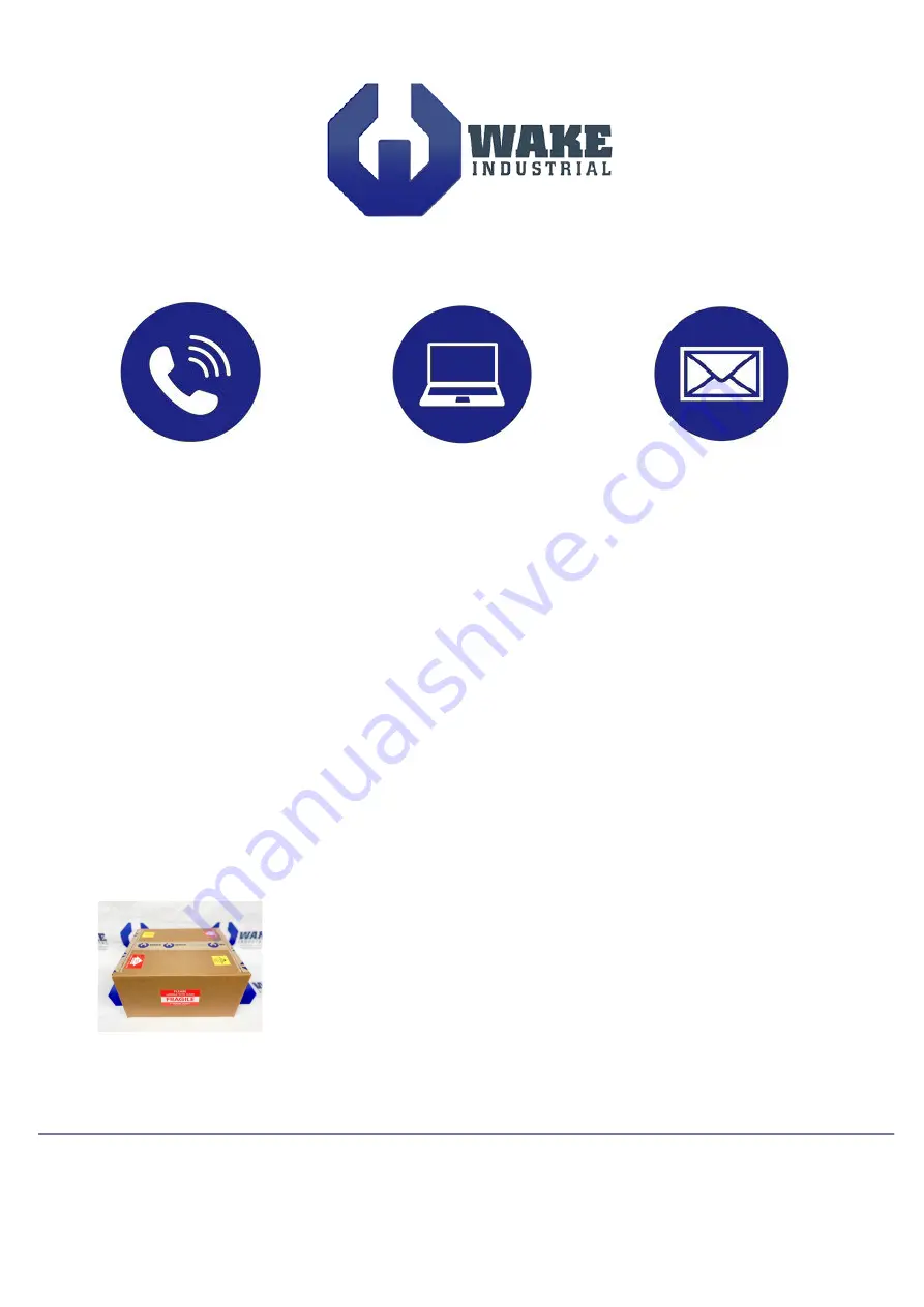
Damage Free Delivery

All of our products are cleaned, go through quality control and are


shipped using a custom military


grade foam to ensure your product


arrives  undamaged.


We  have  the  capability  to  ship  both


small


1lb  products  and  large  200lb+


automation  parts


regardless of your location.

www.wakeindustrial.com

Visit Our Website

Wake Industrial is not affiliated


with nor an authorized distributor


or representative of any


manufacturers, brands or


products listed.

All Products from Wake Industrial, LLC, come with:

Sales and Repairs                       Fast Shipping

 Quality Guarantee

With standards like our 1 year


warranty on ALL products, we


can

 guarantee

 a

 better


customer  service  experience


than any other company


within


our industry.

8 a.m. - 5 p.m. Sales Available


International: 1-919-443-0207


Toll Free: 1-888-551-3082

We  specialize  in  providing  
immediate product delivery  
when  your  system  goes


down. We have thousands 
of

 In-Stock

 automation


products  and  offer  a  full


range of repair options.

Summary of Contents for Rexroth EcoDrive Cs DKC-004 Series

Page 1: ...lity to ship both small 1lb products and large 200lb automation parts regardless of your location www wakeindustrial com Visit Our Website Wake Industrial is not affiliated with nor an authorized distributor or representative of any manufacturers brands or products listed All Products from Wake Industrial LLC come with Sales and Repairs Fast Shipping Quality Guarantee With standards like our 1 yea...

Page 2: ...inear Motion and Assembly Technologies Pneumatics Service Rexroth EcoDrive Cs Drives R911320343 Edition 01 Instruction Manual Courtesy of CMA Flodyne Hydradyne Motion Control Hydraulic Pneumatic Electrical Mechanical 800 426 5480 www cmafh com ...

Page 3: ...ved in the event of the grant of a patent or the registration of a utility model or design DIN 34 1 The specified data is for product description purposes only and may not be deemed to be guaranteed unless expressly confirmed in the contract All rights are reserved with respect to the content of this documentation and the availability of the product Bosch Rexroth AG Bgm Dr Nebel Str 2 D 97816 Lohr...

Page 4: ...ollers without Master Communication Basic Devices 2 3 Master Communication 2 3 Motor MSM020B 2 4 Motor MSM030 2 5 Motor MSM040B 2 6 2 2 Type Plates 2 7 Drive Controller 2 7 Motor 2 7 2 3 Drive Controller Motor Combinations 2 8 2 4 Scope of Supply 2 8 3 Ratings and Dimensions 3 1 4 Reference Documentations 4 1 4 1 Overview 4 1 5 Instructions for Use 5 1 5 1 Overcurrent Protection 5 1 5 2 Connection...

Page 5: ... 5 9 Connecting the Motor 5 11 4 3 Startup Operation and Maintenance 5 11 Startup 5 11 Operation 5 12 Maintenance 5 12 4 4 Installation 5 16 General Information on How to Install the Drive Controller 5 16 Sizing of Enclosure and Control Cabinet 5 18 6 Index 6 1 Courtesy of CMA Flodyne Hydradyne Motion Control Hydraulic Pneumatic Electrical Mechanical 800 426 5480 www cmafh com ...

Page 6: ...the requirements of safe work practices These persons must have adequate safety equipment and be trained in first aid Technical data connections and operational conditions are specified in the reference documentations for the product and must be followed at all times If the products take the form of hardware then they must remain in their original state in other words no structural changes are per...

Page 7: ...rs and guards provided with the equipment properly before switching the device on Before switching the equipment on cover and safeguard live parts safely to prevent contact with those parts A residual current operated circuit breaker or r c d cannot be used for electric drives Indirect contact must be prevented by other means for example by an overcurrent protective device according to the relevan...

Page 8: ...se safety guards use protective coverings install light curtains or light barriers Fences and coverings must be strong enough to resist maximum possible momentum Mount the emergency stop switch in the immediate reach of the operator Verify that the emergency stop works before startup Don t operate the device if the emergency stop is not working Isolate the drive power connection by means of an eme...

Page 9: ... not touch surfaces of device housings and chokes in the proximity of heat sources Danger of burns Do not touch housing surfaces of motors Danger of burns According to operating conditions temperatures can be higher than 60 C 140 F during or after operation Before accessing motors after having switched them off let them cool down for a sufficiently long time Cooling down can require up to 140 minu...

Page 10: ...inal voltage 5 1 DC 300 V 3 6 Firmware 6 1 Multi interface general purpose MGP 7 Firmware version 7 1 e g 01 01 8 Nature of the firmware 8 1 Standard V 9 Firmware release status update 00 to 99 9 1 Release status the currently valid status status of the items list delivered RS Illustration example DKC01 3 XXX 3 1 2 3 4 6 7 8 9 1 0 5 1 2 3 4 6 7 8 9 2 0 5 1 2 3 4 6 7 8 9 3 0 5 1 2 3 4 6 7 8 9 4 0 5...

Page 11: ... 7 1 e g 01 01 8 Nature of the firmware 8 1 Standard V 9 Firmware release status update 00 to 99 9 1 Release status the currently valid status status of the items list delivered RS Illustration example DKC02 3 XXX 3 1 2 3 4 6 7 8 9 1 0 5 1 2 3 4 6 7 8 9 2 0 5 1 2 3 4 6 7 8 9 3 0 5 1 2 3 4 6 7 8 9 4 0 5 Example Abbrev Column D K C 0 2 3 0 0 4 3 M G P 0 1 V R S Fig 2 2 Type code for drive controller...

Page 12: ... 3 4 6 7 8 9 1 0 5 1 2 3 4 6 7 8 9 2 0 5 1 2 3 4 6 7 8 9 3 0 5 1 2 3 4 6 7 8 9 4 0 5 Example Abbrev Column D K C 1 0 3 0 0 4 3 M G P 0 1 V R S Fig 2 3 Type code for drive controllers without master communication basic devices Master Communication 1 Product 1 1 ECM ECM 2 Line 2 1 1 01 3 Design 3 1 1 1 4 Interface 4 1 CANopen CN01 4 2 DeviceNet open style DN01 4 3 DeviceNet micro style DN02 4 4 none...

Page 13: ... without blower NN 6 Encoder 6 1 Incremental encoder C0 6 2 Multiturn absolute encoder M0 7 Electrical connection 7 1 cable tail C 8 Shaft 8 1 key per DIN 6885 1 C 8 2 plain shaft G 9 Holding brake 9 1 without holding brake 0 9 2 electrical release 0 29 Nm 1 10 Standard reference Standard Title Edition DIN 6885 1 Drive Type with Fastenings without Taper Action 1968 08 Parallel Keys Keyways Deep Pa...

Page 14: ...convection without blower NN 6 Encoder 6 1 Incremental encoder C0 6 2 Multiturn absolute encoder M0 7 Electrical connection 7 1 cable tail C 8 Shaft 8 1 key per DIN 6885 1 C 8 2 plain shaft G 9 Holding brake 9 1 without holding brake 0 9 2 electrical release 1 27 Nm 1 10 Standard reference Standard Title Edition DIN 6885 1 Drive Type with Fastenings without Taper Action 1968 08 Parallel Keys Keywa...

Page 15: ... without blower NN 6 Encoder 6 1 Incremental encoder C0 6 2 Multiturn absolute encoder M0 7 Electrical connection 7 1 cable tail C 8 Shaft 8 1 key per DIN 6885 1 C 8 2 plain shaft G 9 Holding brake 9 1 without holding brake 0 9 2 electrical release 2 45 Nm 1 10 Standard reference Standard Title Edition DIN 6885 1 Drive Type with Fastenings without Taper Action 1968 08 Parallel Keys Keyways Deep Pa...

Page 16: ...Power INPUT OUTPUT 200 230V 37V 3 3 1 1A 1 5A 50 60Hz 0 333 3Hz 200W 123456 Rexroth Indramat GmbH DKC02 3 001 3 MGP 01VRS E164620 QR Producing Country MadeinChina Prefix Fig 2 8 Type plate 1 Motor typenschild_motor_text_en fh7 Company name Example K40 02 means week 40 in year 2002 Production week Part number Producing Country Motor type Barcode Hardwareindex A15 SN295553 F1234 Continued Number Ide...

Page 17: ...lute plain shaft with brake 200 W absolute key without brake 200 W absolute key with brake DKCxx x 012 MSM030C 0300 NN C0 CG0 MSM030C 0300 NN C0 CG1 MSM030C 0300 NN C0 CC0 MSM030C 0300 NN C0 CC1 MSM030C 0300 NN M0 CG0 MSM030C 0300 NN M0 CG1 MSM030C 0300 NN M0 CC0 MSM030C 0300 NN M0 CC1 400 W incremental plain shaft without brake 400 W incremental plain shaft with brake 400 W incremental key withou...

Page 18: ...put UL 6 UN3 V 24 ac rated power consumption control voltage input without holding brake without control section at UN3 DC 24 V UL 7 PN3 W n a n a n a n a short circuit current rating SCCR symmetrical amperes UL 8 ISCCR A rms 5000 rated input voltage power UL 9 V 200 230 ac 200 240 ac tolerance rated input voltage UL n a n a n a n a input number of phases UL 3 1 3 1 3 1 3 input frequency UL fLN Hz...

Page 19: ...ries shall be used with listed AC input line fuses or listed circuit breakers specified in this documentation 9 Mains input L1 L2 L3 10 at PDC_cont 11 class J branch circuit fuse 12 find value for tightening torque in project planning manual electrical terminals 13 copper wire PVC insulation conductor temperature 90 C Table 13 5 1 Ta 40 C 14 depending on switching frequency which was set in parame...

Page 20: ...01VRS WA01 EN P 1 In the document typecodes xx is a wild card for the current edition of the documentation example PR01 is the first edition of a Project Planning Manual Fig 4 1 Documentations Overview 5 Instructions for Use 5 1 Overcurrent Protection Branch circuit protection has to be provided externally according to the maximum values voltage and current or voltage and percent of FLA of the fus...

Page 21: ...e Rexroth EcoDrive Cs DOK ECODR3 DKC CS UL IB01 EN P 5 2 Connections Wiring Diagram Fig 5 2 Wiring diagram Courtesy of CMA Flodyne Hydradyne Motion Control Hydraulic Pneumatic Electrical Mechanical 800 426 5480 www cmafh com ...

Page 22: ...ith more than 50 V Before starting to work on the drive controller switch off the voltage supply via the main switch or the circuit breaker Always mount or dismount both connectors motor connection and mains connection at the drive controller Observe the notes in the Important Notes chapter Courtesy of CMA Flodyne Hydradyne Motion Control Hydraulic Pneumatic Electrical Mechanical 800 426 5480 www ...

Page 23: ...cket on connector Fig 5 5 Design Max connectable cross section mm Cross section in AWG gauge No 2 5 12 Fig 5 6 Connection cross section X2 Additional Choke and Braking Resistor Technical Data of the Terminal Connector schnittstellen_X2 fh7 TX RX S20 2 1 ON X4 X5 X6 9 8 7 6 5 4 3 2 1 9 8 7 6 5 4 3 2 1 ADDRESS NODE 0 0 Rexroth ECODRIVE Cs S1 H1 S2 S3 LINE ERROR X20 X21 X4 X5_3 X5_2 X5_1 INPUTíF200V ...

Page 24: ...xroth EcoDrive Cs drives device external X2_Dx FH7 X2 DL1 DL2 DL1 DL2 device internal Fig 5 10 Connection for choke RB1 RB2 RB3 Braking Resistor Note The internal braking resistor causes a derating of the continuous DC bus power By connecting an external braking resistor the derating of the continuous DC bus power can be prevented Note When an external braking resistor is used the drive has to be ...

Page 25: ...xternal device internal Fig 5 12 Jumper on RB2 and RB3 X3 Motor DANGER Lethal electric shock caused by live parts with more than 50 V Before starting to work on the drive controller switch off the voltage supply via the main switch or the fuse Always mount or dismount both connectors motor connection and mains connection at the drive controller Observe the notes in the Important Notes chapter Brak...

Page 26: ...No 0 75 2 18 14 Fig 5 15 Connection cross section For connecting drive controller and motor please use the appropriate Rexroth motor power cables Cable length The maximum cable length is 40 m with ready made Rexroth cable ambient temperature of 40 C according to EN 60204 maximum switching frequency of 8 kHz WARNING No warranty If cables manufactured by a company other than Bosch Rexroth resp cable...

Page 27: ...ector Fig 5 16 Equipment grounding conductor connection Type Number Type of design terminal block 2 threaded terminal end for M4 ring cable lugs Fig 5 17 Design Cross section single core mm Max cross section in AWG gauge No 2 0 14 Fig 5 18 Connection cross section Contrary to the safety instruction in chapter 1 1 a copper conductor cross section of 2 mm2 would be sufficient Maximum 1 m Connection ...

Page 28: ...nal braking catching clamping mechanism or providing sufficient counterbalance for the axis Switching performance see Functional Description of firmware Technical Data of the Terminal Connector schnittstellen_X53 fh7 TX RX S20 2 1 ON X4 X5 X6 9 8 7 6 5 4 3 2 1 9 8 7 6 5 4 3 2 1 ADDRESS NODE 0 0 Rexroth ECODRIVE Cs S1 H1 S2 S3 LINE ERROR X20 X21 X4 X5_3 X5_2 X5_1 INPUTíF200V 240V X3 X2 X1 X6 BR BR ...

Page 29: ...Other drive controllers have to be connected to the voltage source in star shaped form CAUTION Risk of damage The maximum allowed current load of the terminal connectors for the voltage supply of the brake and the control voltage supply must also be observed in the case of a short circuit max voltage at X5_3 1 referring to X5_3 2 36 V current consumption at X5_3 3 and required supply voltage see P...

Page 30: ...ctable dangerous situations or lead to physical damage Therefore Connect and disconnect plug connectors only when they are dry and de energized During operation of the system all plug connectors must be securely tightened WARNING Risk of short circuit caused by liquid coolant or lubricant Short circuits of live lines may cause unpredictable dangerous situations or lead to physical damage Therefore...

Page 31: ...he Functional Description of the particular firmware MGPxxVRS Request the corresponding product documentation from your local sales office Operation Ensure that the ambient conditions are kept during operation Maintenance Cleaning Excessive dirt dust or shavings may affect the function of the motors adversely may in extreme cases even cause a failure of the motors For that reason you should clean ...

Page 32: ...k up the encoder signals The battery is set into the drive controller Exception Rexroth Cartesian Motion Systems CMS The drive controller observes voltage of battery and gives just in time a warning F248 Low battery voltage The service life of the battery depends on the ratio of switch ON duration to switch OFF duration OFF ON t t I tON duration the drive controller is switched on tOFF duration th...

Page 33: ...available for changing the battery is limited batterie_pufferzeit FH7 capacitor voltage V 3 0 554 792 79 2 0 4 0 5 0 A B C D time s A operating hours 3000 backup time 79 s B operating hours 1000 backup time 554 s C operating hours 0 condition as supplied backup time 792 s D range of battery undervoltage 2 3 to 2 7 V Fig 5 26 Backup time of supply voltage During this time the supply voltage of the ...

Page 34: ...r with Rexroth Cartesian Motion Systems CMS regard the instructions of the CMS manual RE 82 674 now 1 Push battery cover downwards and remove cover batteriefach fh7 X21 X20 TX RX S20 2 1 ON X1 X2 X3 2 Remove old battery 3 If not already done so refresh new battery now see instructions above 4 Insert new battery Courtesy of CMA Flodyne Hydradyne Motion Control Hydraulic Pneumatic Electrical Mechani...

Page 35: ...ople and or tools is discharged across them Therefore please note the following information CAUTION Electrostatic charges can cause damage to electronic components and interfere with their operational safety Exposed conductive parts coming into contact with components and circuit boards must be discharged by means of grounding Otherwise errors may occur when triggering motors and moving elements S...

Page 36: ...r leads to low voltages or allow them to come into contact with these When carrying out a high voltage test or an applied overvoltage withstand test on the machine s electrical equipment disconnect all connections to the devices This protects the electronic components allowed in accordance with EN 60204 1 During their routine testing Rexroth drive components are tested for high voltage and insulat...

Page 37: ...tlet air to cooling unit supply air from cooling unit Fig 5 27 Example of arrangement for multiple line structure with components Arrangement of Cooling Units CAUTION Possible damage to the drive controller Operational safety of the machine endangered Note the following instructions Due to the operating principle condensation water is formed when cooling units are used For this reason please obser...

Page 38: ...5 29 Arranging the cooling unit at the front of the control cabinet Moisture condensation occurs when the temperature of the device is lower than the ambient temperature Set cooling units with temperature adjustment to the maximum surrounding temperature and not lower Set cooling units with follow up temperature in such a way that the interior temperature of the control cabinet is no lower than th...

Page 39: ...ted with the doors open commissioning servicing etc it is essential to ensure that after the doors are closed the drive controllers cannot at any time be cooler than the air in the control cabinet as otherwise moisture condensation can occur For this reason sufficient circulation must be provided inside the control cabinet to avoid pockets of heat Courtesy of CMA Flodyne Hydradyne Motion Control H...

Page 40: ...tor 2 8 connection braking resistor 5 5 choke 5 5 equipment grounding conductor 5 8 holding brake 5 9 motor 5 6 Connection Diagram 5 3 control cabinet with multiple line structure 5 18 cooling ribs 5 12 cooling units 5 18 D Dimensions 3 1 DL1 DL2 5 5 Documentations 4 1 dripping or sprayed water 5 18 drive controller combination with motors 2 8 index 2 7 serial number 2 7 E EcoDrive Cs type codes 2...

Page 41: ...ontrollers 2 8 connection 5 6 maintenance 5 12 operation 5 12 serial number 2 7 startup 5 11 type code MSM020B 2 4 type code MSM030 2 5 type code MSM040B 2 6 MSM020B type code 2 4 MSM030 type code 2 5 MSM040B type code 2 6 O Overcurrent Protection 5 1 R Ratings 3 1 RB1 RB2 RB3 5 5 Reference Documentations 4 1 refresh battery 5 14 S Safety Instructions 1 1 serial number drive controller 2 7 motor 2...

Page 42: ...master communication 2 3 master communication 2 3 motor MSM020B 2 4 motor MSM030 2 5 motor MSM040B 2 6 Type codes 2 1 Type plates 2 7 U U V W 5 7 Use appropriate 1 4 W Wiring Diagram 5 2 X X1 5 3 X2 5 4 X3 5 6 X5_3 5 9 Courtesy of CMA Flodyne Hydradyne Motion Control Hydraulic Pneumatic Electrical Mechanical 800 426 5480 www cmafh com ...

Page 43: ...6 4 Index Rexroth EcoDrive Cs DOK ECODR3 DKC CS UL IB01 EN P Courtesy of CMA Flodyne Hydradyne Motion Control Hydraulic Pneumatic Electrical Mechanical 800 426 5480 www cmafh com ...

Page 44: ...Courtesy of CMA Flodyne Hydradyne Motion Control Hydraulic Pneumatic Electrical Mechanical 800 426 5480 www cmafh com ...

Page 45: ... 57 97803 Lohr Germany Bgm Dr Nebel Str 2 97816 Lohr Germany Phone 49 0 93 52 40 50 60 Fax 49 0 93 52 40 49 41 service svc boschrexroth de www boschrexroth com Courtesy of CMA Flodyne Hydradyne Motion Control Hydraulic Pneumatic Electrical Mechanical 800 426 5480 www cmafh com ...

Reviews: