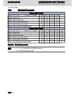


● For EMC-optimal installation in the control cabinet, use a separate con‐
trol cabinet panel for the drive components.
● Frequency converters need to be mounted in metal cabinet and con‐
nected to power supply with grounding.
● For frequency converters with internal filter, 15 m shielded cable was
used between the motor and frequency converter in the EMC test.
● For the end application system with frequency converters, the conformi‐
ty of EMC directions needs to be confirmed.
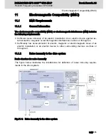
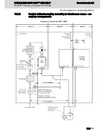
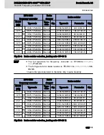
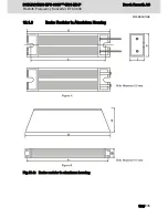
Division into Areas (zones)
Exemplary arrangements in the control cabinet: See
fig. 11-7 "Control cabinet mounting
according to interference areas – exemplary arrangements" on page 159
.
We distinguish three areas:
1. Interference-free area of control cabinet (area A):
This includes:
● Supply feeder, input terminals, fuse, main switch, mains side of mains filter for
drives and corresponding connecting lines;
● Control voltage or auxiliary voltage connection with power supply unit, fuse
and other parts unless connection is run via the mains filter of the AC drives;
● All components that are not electrically connected with the drive system.
2. Interference-susceptible area (area B):
● Mains connections between drive system and mains filter for drives, mains
contactor;
● Interface lines of drive controller
3. Strongly interference-susceptible area (area C):
● Motor power cables including single cores
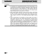
Never run lines of one of these areas in parallel with lines of another area so that there
is not any unwanted interference injection from one area to the other and that the filter
is jumped with regard to high frequency. Use the shortest possible connecting lines.
Recommendation for complex systems: Install drive components in one cabinet and the
control units in a second, separate cabinet.
Badly grounded control cabinet doors act as antennas. Therefore, connect the control
cabinet doors to the cabinet on top, in the middle and on the bottom via short equip‐
ment grounding conductors with a cross section of at least 6 mm
2
or, even better, via
grounding straps with the same cross section. Make sure connection points have good
contact.
Bosch Rexroth AG
Electromagnetic Compatibility (EMC)
DOK-RCON03-EFC-3600***-IT01-EN-P
Rexroth Frequency Converter EFC 3600
158/235
Summary of Contents for Rexroth EFC 3600
Page 6: ...Bosch Rexroth AG DOK RCON03 EFC 3600 IT01 EN P Rexroth Frequency Converter EFC 3600 IV 235 ...
Page 232: ...230 235 ...
Page 236: ...Bosch Rexroth AG DOK RCON03 EFC 3600 IT01 EN P Rexroth Frequency Converter EFC 3600 234 235 ...
Page 237: ...Notes DOK RCON03 EFC 3600 IT01 EN P Rexroth Frequency Converter EFC 3600 Bosch Rexroth AG ...


