5
Mounting, demounting and electric installation
5.1
Mounting and demounting
5.1.1
Unpacking the module
Module damage due to electrostatic dis‐
charge
NOTICE
Comply with the required safety measures against electrostatic discharge
(ESD) acc. to EN 61340-5-1 and IEC 61340-5-2 when handling the module.
Read the package insert of the module and follow the instructions.
Only qualified staff is allowed to mount and demount the module.
5.1.2
Preparation and mounting
Unintended machine startup due to installa‐
tion works without to ensure that there is no
voltage applied.
WARNING
●
Disconnect the complete IndraControl S20 station and secure the sys‐
tem against restart before mounting or demounting the module.
●
Connect the voltage only after the system has been set up completely
and ensure that there is no hazard originating from the station or the
system. Observe the diagnostic displays and possible diagnostic mes‐
sages.
Install the module in a dust- and humidity-proof control cabinet or terminal
box (IP 54 or higher) on a 35 mm mounting rail.
Protect the control cabinet or the terminal box against opening by unauthor‐
ized parties.
To connect the cables, only use the IndraControl S20 plugs provided upon
delivery.
5.1.3
Setting DIP switch
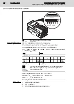
A DIP switch is located on the upper side of the module.
DOK-CONTRL-S20*SSDO*8*-AP02-EN-P
Bosch Rexroth AG
23/85
IndraControl S20 Module With Safe Digital Outputs S20-SSDO-8/3
Mounting, demounting and electric installation

