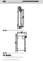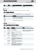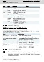
The distances of the mounting holes are listed in
the CDI+ splitter – Rear view" on page 16
Use two M5 screws to fasten the CDI+ splitter.
2. Fixing the cables
Unfixed cables are not permitted. Therefore, an appropriate fixing (e. g. in-
stallation in a cable channel) and a strain relief of the cables is required.
10.4 Demounting
1. Disconnect the CDI+ splitter from voltage.
2. Remove all connected cables including the cable at the function earth con-
nection.
3. Loosen both screws used to attach the CDI+ splitter box to the rear panel.
4. Lift the CDI+ splitter vertically and remove it from the rear panel.
10.5 Electric connection
10.5.1 Procedure to connect the lines to X1S1
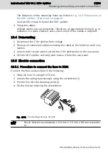
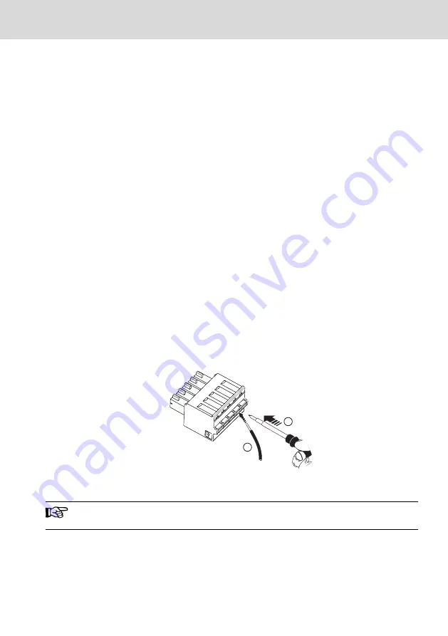
Connect the lines as described in the following:
1. Strip the lines to a length of 9 mm.
2. Loosen the spring by pressing it using the screwdriver
①
.
3. Put the line into the clamping point
②
.
4. Fix the line by removing the screwdriver.
1
1
i
g
i
t
a
l
I
n
p
1
2
Fig. 10-5: Connecting the lines at X1S1
Bosch Rexroth recommends a 0.4 mm x 2.5 mm x 80 mm screwdriv-
er.
IndraControl VAC 08.1 CDI+ Splitter
17/33
Mounting, demounting and electric installation
R911400465_Edition 01 Bosch Rexroth AG
Summary of Contents for rexroth IndraControl VAC 08.1
Page 1: ...IndraControl VAC 08 1 CDI Splitter Operating Instructions R911400465 Edition 01 ...
Page 6: ...IV IndraControl VAC 08 1 CDI Splitter Bosch Rexroth AG R911400465_Edition 01 ...
Page 36: ...30 33 IndraControl VAC 08 1 CDI Splitter Bosch Rexroth AG R911400465_Edition 01 ...
Page 39: ...Notes IndraControl VAC 08 1 CDI Splitter 33 33 ...


