●
The LED displays must not be covered.
●
Provide the following minimum distances for installation and sufficient
cooling:
–
To the bottom side 50 mm
–
To the top side 80 mm
●
Lay all connecting cables in loops.
●
Use strain reliefs for the cables.
●
Keep as much distance as possible to noise sources, when installing the
VAU 01.1U.
5.3.2
Mounting
Mounting the UPS on the mount‐
ing rail
Only mounting rails TH 35-7.5 and TH 35-15 made of steel ac‐
cording to EN 60715 are permitted.
Determine the distance of the mounting holes according to EN 60715 appen‐
dix B.
Hang the UPS onto the mounting rail from above. Then exert slight pressure
to engage the UPS in the lower section of the housing.
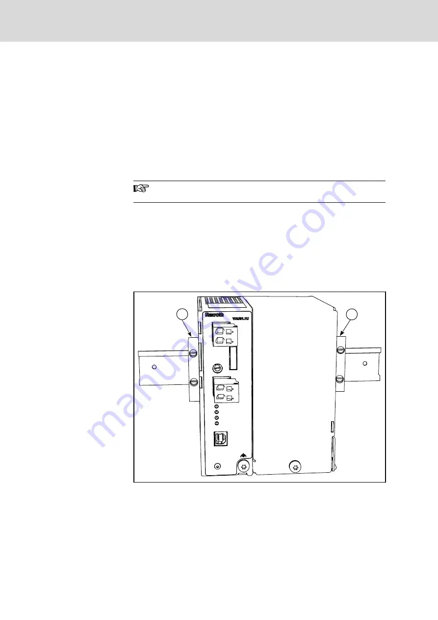
Attaching the end clamps
Mount end clamps on the mounting rail on both sides of the VAU 01.1U to
avoid lateral moving of the UPS if vibrations occur. The end clamps are avail‐
able as accessories, see
chapter 9.2 "Accessories" on page 54
24V In
0 V In
X1S1
F1
S1
X1S2
XUSB In
24V Out
0 V Out
USV OK
PC OK
Batt. Charg.
Batt. Low
1
1
①
End clamps on the mounting rail
Fig.5-3:
End clamps
Bosch Rexroth AG
DOK-SUPPL*-VAU*01.1U**-PR03-EN-P
Rexroth IndraControl VAU 01.1U UPS with USB interface
26/63
Dimensions, Mounting and Dismounting


