4. Plug the cable grommet into the housing.
5. Provide the cables, which are lead through a cable grommet, with a strain
relief.
6. Cover not used openings with a dummy sleeve.
7. Check that the seal of the cover is not damaged.
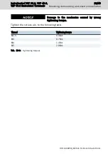
8. Position the cover properly and fasten the screws with the corresponding
tightening torque (refer to
tab. 10-3 "Tightening torques" on page 23
Cable grommet name
(Assembling kit/putty)
Cable diameter
QT4
4-5 mm
QT5
5-6 mm
QT6
6-7 mm
QT7
7-8 mm
QT8
8-9 mm
QT11
11-12 mm
QT12
12-13 mm
QTB
Dummy sleeve
Tab. 10-4: Cable diameter and corresponding cable grommets
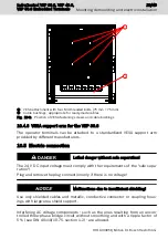
10.4.2 Attaching to standardized VESA support arm at the VEP 30.6
Observe the minimum bending radius of the cables used.
Use appropriate cable material (sufficient bending and torsional
strength).
28/49
Mounting, demounting and electric installation
IndraControl VEP 30.6, VEP 40.6,
VEP 50.6 Embedded Terminals
Bosch Rexroth AG R911403058_Edition 01


